P746/EN OP/G31
Operation
(OP) 5-
12
MiCOM
P746
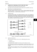
1.3.2.1.6 Internally Initiated CBF i.e.
Tripping from the Differential Element 87BB
When a tripping order is generated by the busbar protection (87BB or 50BF) but not
executed due to a circuit breaker failure condition, the following circuit breakers are required
to be tripped instead:
All the circuit breakers in the adjacent busbar zone if the faulty circuit breaker is that of a bus
coupler or bus section.
Optional: The remote end circuit breaker if the faulty circuit breaker is that of a feeder (line or
transformer). This intertripping is done via PSL and may not be required on feeders, which
may be serviced automatically via the distance or other line protection.
The tripping order from the busbar protection is referenced as Tp
ABC
, it is always three-phase
and initiates timers tBF1 and tBF2. The first timer is associated with the local re-trip function
while the second timer is associated with the conveyance of the signal for tripping of the
adjacent zone in the cases of bus coupler/bus section circuit breaker failure.
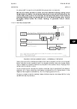
1.3.2.1.6.1 Description of the Logic for Internally Initiated CBF
OP
I <
Dead pole detection threshold
Local overcurrent element CBF confirmation
Main busbar protection trip signal
(note2)
I
I>BB
>
Local oversurrent element CBF confi
r mation
&
&
&
:Tripping signal from 87BB
T
pABC
tBF1
tBF2-tBF1
&
BBx
Local
Retrip
Local
Circuit
Breaker
Note 1: Signal for back
k
-trip (including adjacent zone(s) if failed CB is bus section or bus coupler circuit breaker
Note 2: I>BB and I> could be enabled or disabled (scheme shown is with the 2 functions enhanced)
Back trip
(Note 1)
Trip signal
P3971ENb
FIGURE 5: CB FAIL ELEMENT LOGIC – INTERNALLY INITIATED
1.3.2.1.6.2 Initial Trip
A trip signal is issued and then confirmed. If the (optional) threshold for the local Overcurrent
protection setting for busbar protection (
I
>BB) is exceeded then the local circuit breaker trip
coil is energised and subsequently the local circuit breaker is tripped.
1.3.2.1.6.3 Re-Trip after time tBF1
The dead pole detection threshold (
I
<) and external protection initiation (
I
>) trigger the first
breaker failure timer (tBF1). This signal in turn is passed through an AND gate with the
signal from the local Overcurrent protection for busbar protection (
I
>BB) (if a circuit breaker
failure condition has evolved this will still be present) and a re-trip command is issued. Re-
trip output contacts should be assigned using the PSL editor (including in default PSL
settings).
1.3.2.1.6.4 Back-Trip after time tBF2
A signal from the first circuit breaker timer triggers the second breaker failure timer (tBF2).
This in turn is passed through an AND gate with the signal from the local overcurrent
protection for busbar protection (
I
>BB), if a circuit breaker failure condition has persisted this
will still be present, and a general bus-zone back-trip signal issued.
Содержание MiCOM P746
Страница 4: ......
Страница 5: ...Pxxx EN SS G11 SAFETY SECTION...
Страница 6: ......
Страница 8: ...Pxxx EN SS G11 Page 2 8 Safety Section BLANK PAGE...
Страница 16: ...P746 EN IT G31 Introduction MiCOM P746...
Страница 18: ...P746 EN IT G31 Introduction IT 1 2 MiCOM P746 IT BLANK PAGE...
Страница 26: ...P746 EN TD G31 Technical Data MiCOM P746...
Страница 38: ...P746 EN GS G31 Getting Started MiCOM P746...
Страница 78: ...P746 EN ST G31 Getting Started MiCOM P746...
Страница 80: ...P746 EN ST G31 Settings ST 4 2 MiCOM P746 ST BLANK PAGE...
Страница 112: ...P746 EN ST G31 Settings ST 4 34 MiCOM P746 ST BLANK PAGE...
Страница 114: ...P746 EN OP G31 Operation MiCOM P746...
Страница 136: ...P746 EN OP G31 Operation OP 5 22 MiCOM P746 OP BLANK PAGE...
Страница 138: ...P746 EN AP G31 Application Notes MiCOM P746...
Страница 142: ...P746 EN AP G31 Application Notes AP 6 4 MiCOM P746 AP BLANK PAGE...
Страница 194: ...P746 EN AP G31 Application Notes AP 6 56 MiCOM P746 AP BLANK PAGE...
Страница 196: ...P746 EN PL G31 Programmable Logic MiCOM P746...
Страница 238: ...P746 EN MR A11 Measurements and Recording MiCOM P746...
Страница 240: ...P746 EN MR A11 Measurements and Recording MR 8 2 MiCOM P746 MR BLANK PAGE...
Страница 258: ...P746 EN FD G31 Firmware Design MiCOM P746...
Страница 280: ......
Страница 342: ...P746 EN CM F21 Commissioning and Maintenance CM 10 62 MiCOM P746 CM Commissioning Engineer Customer Witness Date Date...
Страница 348: ...P746 EN MT A11 Maintenance MiCOM P746...
Страница 350: ...P746 EN MT A11 Maintenance MT 11 2 MiCOM P746 MT BLANK PAGE...
Страница 364: ...P746 EN MT A11 Maintenance MT 11 16 MiCOM P746 MT BLANK PAGE...
Страница 366: ...P746 EN TS G31 Troubleshooting MiCOM P746...
Страница 368: ...P746 EN TS G31 Troubleshooting TS 12 2 MiCOM P746 TS BLANK PAGE...
Страница 382: ...P746 EN SC G31 SCADA Communications MiCOM P746...
Страница 424: ...P746 EN SC G31 SCADA Communications SC 13 42 MiCOM P746 SC BLANK PAGE...
Страница 426: ...P746 EN SG F21 Symbols and Glossary MiCOM P746...
Страница 438: ......
Страница 440: ...P746 EN IN G31 Installation IN 15 2 MiCOM P746 IN BLANK PAGE...
Страница 465: ...Installation P746 EN IN G31 MiCOM P746 IN 15 27 IN 10P74611 1 FIGURE 18 MiCOM P746 80TE WIRING DESCRIPTION P746xxxL...
Страница 468: ......
Страница 470: ...P746 EN HI G31 Remote HMI HI 16 2 MiCOM P746 HI BLANK PAGE...
Страница 500: ...P746 EN HI G31 Remote HMI HI 16 32 MiCOM P746 HI BLANK PAGE...
Страница 502: ......
Страница 504: ...P746 EN CS A11G31 Cyber Security CS 17 2 MiCOM P746 CS BLANK PAGE...
Страница 524: ...P746 EN VH G31 Firmware and Service Manual Version History MiCOM P746...
Страница 529: ......


