Schäfter+Kirchhoff SK8100U3JRC Скачать руководство пользователя страница 1

SK8100U3JRC


Sample Configuration
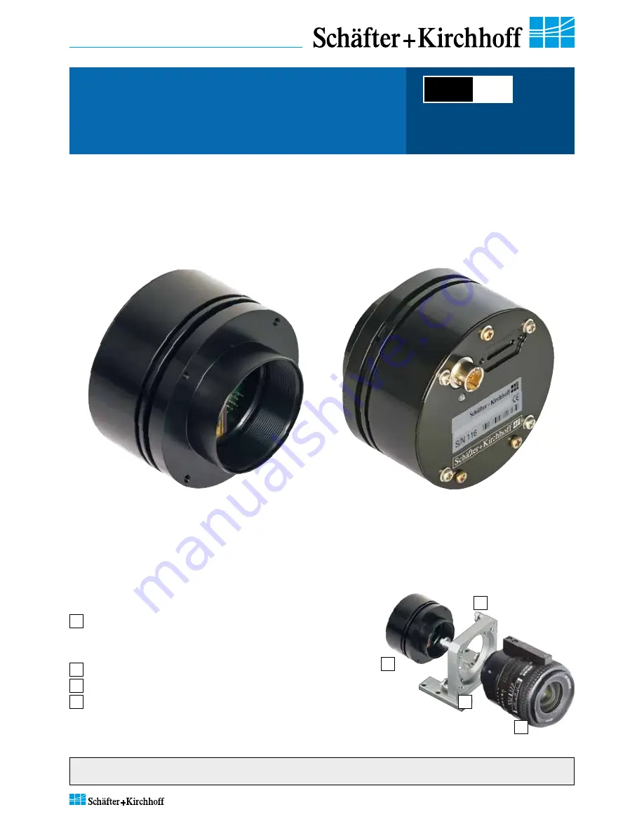
1


CCD line scan camera 


SK8100U3JRC


mounted with

2


Mounting bracket SK5105

3


Clamping claws SK5102

4


Photo lens SK1.4/50-40 


(integrated  focus/aperture adjustment)

2

1

3

4

Schäfter + Kir

chhof

f © 2015

  •  Line Scan Camera SK8100U3JRC Manual (07.2015)  •  shar

ed_Titel_ML.indd (07.2015)

Kieler Str. 212, 22525 Hamburg, Germany  

• 

 Tel: +49 40 85 39 97-0  

• 

 Fax: +49 40 85 39 97-79  

• 

 [email protected]  

  www.SuKHamburg.de

SK8100U3JRC

Color Line Scan Camera

3x 2700 pixels, 8 µm x 8 µm, 24 / 15 MHz pixel frequency

Instruction Manual

07.2015

Read the manual carefully before the initial start-up. For the content table refer to page  3.

The producer reserves the right to change the herein described specifications in case of technical advance of the product.

USB

 3.0

•  Robust cable connections 

•  Hot-pluggable  

•  Perfect for movable setups

Содержание SK8100U3JRC

Страница 1: ...r 212 22525 Hamburg Germany Tel 49 40 85 39 97 0 Fax 49 40 85 39 97 79 info SuKHamburg de www SuKHamburg de SK8100U3JRC Color Line Scan Camera 3x 2700 pixels 8 µm x 8 µm 24 15 MHz pixel frequency Instruction Manual 07 2015 Read the manual carefully before the initial start up For the content table refer to page 3 The producer reserves the right to change the herein described specifications in case...

Страница 2: ...ht sources might be used These can affect your eyesight temporarily or even cause permanent da mage to the eyes or skin Do not look directly into the light beam Mechanical Warning Ensure that the scanner axis is free to move and that no obstacles are in the way especially fingers Do not place any body parts in the way of moving parts For typical use in a scanning application please consider the fo...

Страница 3: ...ming a Scan 10 3 1 Software SkLineScan 10 Function Overview SkLineScan Toolbar Basic Visualization of the Sensor Output 3 2 Adjustments for Optimum Scan Results 12 Lens Focussing Sensor Alignment Gain Offset Control Dialog White Balance and Shading Correction Integration Time Synchronization of the Imaging Procedure and the Object Scan Velocity RGB Sensors 2D Imaging and Pixel Allocation 4 Advance...

Страница 4: ... the SkLineScan program have been loaded from the SK91USB3 WIN CD then the camera can be parameterized The parameters such as integration time synchronization mode or shading correction are permanently stored in the camera even after a power down or disconnection from the PC The oscilloscope display in the SkLineScan program can be used to adjust the focus and aperture settings for evaluating fiel...

Страница 5: ...here are limitations see footer High performance video card PCIe bus Operating System Windows 7 64 or 32 bit CD DVD drive for software installation Sensor category CCD Color Sensor Sensor type ILX724KA Pixel number 3x 2700 Pixel size width x height 8 x 8 µm2 Pixel spacing 8 µm Line spacing line sequence 64 µm red R blue B green G Active sensor length 21 6 mm Anti blooming Integration control x Sha...

Страница 6: ...amera and the optics are ordered as a kit the components are pre assembled and shipped as one unit Keep the protective cap on the lens until the mechanical installation is finished If you must handle with an open sensor or lens surface make sure the environment is as dust free as possible Blow off loose particles using clean compressed air The sensor and lens surfaces can be cleaned with a soft ti...

Страница 7: ...the only connection you have to make For any kind of synchronized operation the external trigger signal s have to be wired to socket 2 A frame synchronization signal and two separate line synchronization signals can be handled The various trigger modes are described in section Synchronization of the Imaging Procedure and the Object Scan Velocity p 17 2 1 3 4 5 6 7 8 9 10 11 12 2 1 3 4 5 6 Synchron...

Страница 8: ...en automatically detected SkLineScan start up dialog Ensure the displayed camera type is identical with the connected line scan camera If necessary shut down the program disconnect the camera and wait a few seconds Then reconnect the camera and start SkLineScan once again The start up dialog also indicates the active USB standard The optimum performance is provided by USB3 0 The camera LED should ...

Страница 9: ...Line Scan Camera SK8100U3JRC Manual 07 2015 shared_blank_2nd Instance indd 07 2015 9 SK8100U3JRC Instruction Manual 07 2015 2015 Schäfter KirchhoffGmbH Hamburg ...

Страница 10: ...put Shif F4 For additional functions see the SK91USB3 WIN software manual Start the SkLineScan program The most common functions of the line scan camera can be controlled by dialog boxes Commands for comprehensive camera functionality can be entered in the Camera Gain Offset Control dialog For a guide on how to carry out imaging and how to work with the obtained data with the Schäfter Kirchhoff so...

Страница 11: ...ling of the x axis corresponds with the number of pixels in the line sensor Line scan in oscilloscope display brightness vs pixel number Zoom Function 4 5 6 7 For high numbers of sensor pixels the limited number of display pixels might be out of range in which case the zoom function can be used to visualize the brightness profile in detail Magnification of one or several sections of the signal all...

Страница 12: ...hanges in the optical system or camera parameters are displayed in real time when using an open dialog box Lens Focussing To focus a line scan camera the variations in edge steepness at dark bright transitions and the modulation of the line scan signal are desisive Adjust the focus using a fully opened aperture to restrict the depth of field and to amplify the effects of focus adjustments A fully ...

Страница 13: ... camera The Camera Control frame on the right is used for commands and advanced software functions 4 1 Camera Control by Commands p 20 2 Adjust channel1 gain and minimize difference between channels using Gain slider 1 Adjust channel1 zero level and minimize diffe rence between channels using Offset slider Offset and gain adjustment for more than one gain offset channel Adjustment principle 1 Offs...

Страница 14: ...t 8 bit resolution and 4095 at 12 bit to provide a flat signal Shading correction with a balanced RGB sensitivity ensures a natural color reading The reference signal is stored in the Shading Correction Memory SCM of the camera and subsequent scans are normalized using the scale factors from this white reference Step 1 Gain Adjustment Use a homogeneous white object e g a white sheet of paper to ac...

Страница 15: ...in the middle column to calculate the reference data basing on the imaging setup Enter the parameters focal length FL sensor length SL and field of view FOV according to your setup The implemented algorithm will compensate the natural lens vignetting Click on Save SCM to Flash to save the SCM reference signal in the flash memory of the camera Step 2 Originating the Shading Correction Data The shad...

Страница 16: ...by two vertical sliders or two input fields in the section Integration time of this dialog The left slider is for a corser the right for finer adjustments The current line frequency is displayed in the Line Frequency status field The adjustment of the integration time in the range of Integration Control shutter with an integration time shorter than the minimum exposure period does not change the l...

Страница 17: ...must be orthogonal to the sensor axis of the CCD line scan camera To obtain a proportional image with the correct aspect ratio a line synchronous transport with the laterally correct pixel assignment is required The line frequency and the constant object velocity have to be adapted to each other In cases of a variable object velocity or for particular high accuracy requirements then an external sy...

Страница 18: ... completition of the previous line scan The line frequency is determined by the programmed value LineStart SK Mode 1 Initiated by the external trigger and the currently exposed line will be read out at the next internal line clock The start and duration of exposure are controlled internally by the camera and are not affected by the trigger The exposure time is programmable and the trigger does not...

Страница 19: ...ed andallcolor informationhasbeenacquired RGB Sensors 2D Imaging and Pixel Allocation A B Monochrome font pattern A line synchronous object transport B asynchronous transport of the object causes color convergence aberration The Camera SK8100U3JRC provides the red R green G and blue B informations se quentially in one single video output signal The co lor information originating from the different...

Страница 20: ...information can be read from the camera using the request commands All set and request commands are listed in the tables below The commands are entered in the Input field in the Camera Control section of the Camera Gain Offset Control user dialog Shift F4 In the Output field either the acknowledgement of the set commands 0 OK 1 not OK or the return values of the request commands are output The par...

Страница 21: ...le DXT decoupling of line clock frequency and exposure time SNES CR enable NES no EEPROM save SCOG CR enable COG coupling of gain1 gain3 RDXT CR disable DXT decoupling of line clock frequency and exposure time RNES CR disable NES no EEPROM save RCOG CR disable COG coupling of gain1 gain3 RESET CR reset Memory to manufacturer default Range of values oooo 0 1023 ppp 0 255 xxxx 4 digits integer value...

Страница 22: ... x 1 1 x x x Sync 1x Enable x x 0 x x x x x Sync 4x Enable x x 1 x x x x x Sync up Enable down disable x 0 x x x x x x Sync up down Enable x 1 x x x x x x Sync Control Disable 0 x x x x x x x Sync Control Enable 1 x x x x x x x 128 64 32 16 8 4 2 1 For diagnostic purposes the present state of external trigger inputs LINE SYNC A LINE SYNC B FRAME SYNC or the internal line counter can be output inst...

Страница 23: ...C 1 Trigger on 4 edges of SyncA and SyncB direction detection on hysteresis 0 Sync Control Register 11100xxx b D 1 Trigger on 4 edges of SyncA and SyncB direction detection on hysteresis 4 Sync Control Register 11101xxx b E 2 1 1 1 machine holdup oscillation 4 Advanced SkLineScan Software Functions Example Timing Diagrams of Advanced Synchronization Control Annotations SyncA LINE SYNC A external l...

Страница 24: ...A indd 07 2015 24 5 Sensor Information SK8100U3JRC Instruction Manual 07 2015 2015 Schäfter KirchhoffGmbH Hamburg 5 Sensor Information Block Diagram Features Pin Configuration Top View Manufacturer Sony Type ILX724KA Data source Sony Linear Sensor Document E99620 PS ...

Страница 25: ...K8100U3JRC Manual 07 2015 shared_Sensor_ILX724KA indd 07 2015 25 5 Sensor Information SK8100U3JRC Instruction Manual 07 2015 2015 Schäfter KirchhoffGmbH Hamburg Example of Representative Characteristics Vdd 12 V Ta 25 C ...

Страница 26: ...an Camera SK8100U3JRC Manual 07 2015 shared_Sensor_ILX724KA indd 07 2015 26 5 Sensor Information SK8100U3JRC Instruction Manual 07 2015 2015 Schäfter KirchhoffGmbH Hamburg Electrooptical Characteristics Note 1 ...

Страница 27: ...Line Scan Camera SK8100U3JRC Manual 07 2015 shared_blank indd 07 2015 27 SK8100U3JRC Instruction Manual 07 2015 2015 Schäfter KirchhoffGmbH Hamburg ...

Страница 28: ...Line Scan Camera SK8100U3JRC Manual 07 2015 shared_blank_3rd Instance indd 07 2015 28 SK8100U3JRC Instruction Manual 07 2015 2015 Schäfter KirchhoffGmbH Hamburg ...

Страница 29: ...camera determine the optical resolution of the system first the pixel configuration of the line sensor and secondly the optical resolution of the lens The worst value is the determining value In a phased set up both are within the same range The optical resolution of the line sensor is primarily deter mined by the number of pixels and secondarily by their size and spacing the inter pixel distance ...

Страница 30: ...Line Scan Camera SK8100U3JRC Manual 07 2015 shared_blank_4th Instance indd 07 2015 30 SK8100U3JRC Instruction Manual 07 2015 2015 Schäfter KirchhoffGmbH Hamburg ...

Страница 31: ...nal conditioning CE Conformity This manual has been prepared and reviewed as carefully as possible but no warranty is given or implied for any errors of fact or in interpretation that may arise If an error is suspected then the reader is kindly requested to inform us for appropriate action The circuits descriptions and tables may be subject to and are not meant to infringe upon the rights of a thi...

Страница 32: ...or setting camera parameters via USB Operating systems Windows 7 x64 and x86 Windows XP SP3 SK91USB3 LV Order Code VI library for LabVIEW USB 3 0 cable SK9020 3 Camera connector USB 3 0 plug type micro B with safety lock screws PC connector USB 3 0 plug type A also fits into a USB 2 0 type A socket SK9020 3 Order Code 3 3m cable length standard 5 5m cable length External synchronization cable SK90...

Отзывы: