User Guide
ECUsim
™
5100
Professional Multiprotocol 3-PIM
OBD-II ECU Simulator
Страница 1: ...User Guide ECUsim 5100 Professional Multiprotocol 3 PIM OBD II ECU Simulator ...
Страница 2: ...ser Guide Information contained in this document is subject to change without notice Trademarks are property of their respective owners 2010 ScanTool net LLC All rights reserved Printed in the United States of America ...
Страница 3: ...t Init 12 6 3 SAE J1850 and ISO 15765 4 12 6 4 Monitoring OBD Traffic 12 6 5 Status Messages 13 7 0 Virtual ECUs 14 7 1 Engine Control Module ECM 15 7 1 1 ECM Mode 1 15 7 1 2 ECM Mode 2 17 7 1 3 ECM Mode 3 17 7 1 4 ECM Mode 4 17 7 1 5 ECM Mode 7 18 7 1 6 ECM Mode 9 18 7 1 7 ECM Mode A 18 7 2 Transmission Control Module TCM 19 7 2 1 TCM Mode 1 19 7 2 2 TCM Mode 3 19 7 2 3 TCM Mode 4 19 7 2 4 TCM Mo...
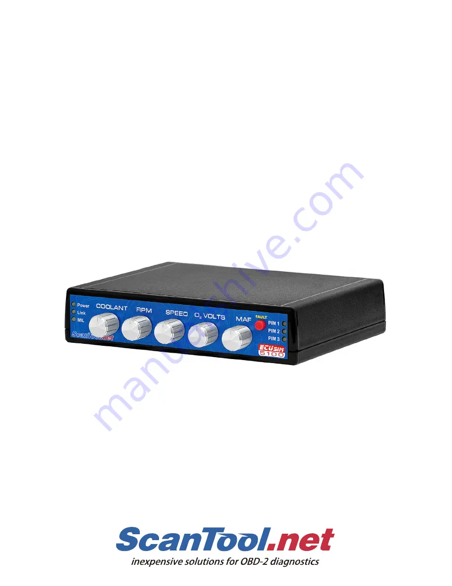
Страница 4: ... assigned to common PIDs a fault event button and indicator lights for power connection and MIL Malfunction Indicator Light Physical connection to the scan tool is made through a standard SAE J1962 female connector The simulator can accept from one to three plug in modules PIMs each configured for a different OBD protocol The user is able to select any one of the three protocols using a three posi...
Страница 5: ...igned to frequently used PIDs o Coolant Temperature o Engine Speed RPM o Vehicle Speed o Oxygen Sensor Voltage o Mass Airflow MAF Fixed SAE J1979 modes and PIDs MIL Link and Power indicators FAULT button USB connection for PIM configuration and OBD traffic monitoring On the fly OBD protocol switching Standard J1962F connector Firmware upgradeable 1 2 Package Contents ECUsim 5100 unit with 1 2 or 3...
Страница 6: ...at least one ECU is initialized The LED dims when an OBD message is received b J1850 and CAN protocols the LED blinks when an OBD message is received 3 Malfunction Indicator Light 4 Knobs assigned to the five commonly used Mode 1 PIDs 5 FAULT button When pressed the following happens a Set MIL and number of stored DTCs Mode 1 PID 01 b Generate pending stored and permanent DTCs c Generate freeze fr...
Страница 7: ... controlled by the PIM Select switch b 5BAUD FAST Selects the type of initialization for ISO 14230 4 Down 5 baud init up fast init c 11 29 BIT Selects the CAN frame ID type Down 11 bit up 29 bit d 250K 500K Selects the CAN baud rate Down 250 kbps up 500 kbps 5 Power jack 12 VDC Use only the provided power supply to power the simulator Using a different power supply may cause permanent damage which...
Страница 8: ...ct switch The corresponding LED on the front panel will turn green 5 Connect the OBD connector of your OBD tester or OBD interface to the DLC 3 2 Using the Simulator Once the simulator is set up and configured you can use the PIM Select switch on the back of the unit to switch between PIM1 PIM2 and PIM3 When you switch to a new PIM two things should happen 1 The corresponding PIM indicator LED sho...
Страница 9: ...on and connect it to any available USB port If the operating system does not find install the drivers automatically you can download them from FTDI s website FTDI Virtual Com Port Drivers http www ftdichip com Drivers VCP htm 4 2 Terminal Setup Almost any serial port terminal emulation program can be used to communicate with the ECUsim Some of the popular terminals include the HyperTerminal RealTe...
Страница 10: ...ay the command prompt The PIM is now ready to accept user commands 5 1 Supported Commands The following is a summary of currently supported commands MON 0 1 OBD bus monitoring off on RESET Reboot the PIM SP x Set OBD protocol MON 0 1 Turn OBD bus monitoring off 0 or on 1 On power up OBD monitoring is on by default Under certain conditions turning off bus monitoring can decrease ECU response time R...
Страница 11: ...of the simulator in different protocol modes It assumes that the simulator is connected to a PC running terminal emulation software 6 1 ISO 9141 2 and ISO 14230 4 5 Baud Init After switching to the ISO 9141 2 protocol or ISO 14230 4 with 5 baud init option the PIM will print the following status message WAITING FOR 5 BAUD INIT It will not respond to any requests until the bus is initialized After ...
Страница 12: ... and ISO 15765 4 Protocols 1 2 and 5 do not require initialization Once the PIM reboots after the set protocol command and prints the configuration summary it will immediately start listening to and responding to OBD requests 6 4 Monitoring OBD Traffic By default each PIM prints incoming and outgoing OBD messages including the message headers but without the checkbyte Here is an example of communi...
Страница 13: ... OVERFLOW UART transmit buffer overflow detected MALFUNCTION EVENT User pressed the FAULT button WAITING FOR 5 BAUD INIT The simulator is waiting for an ISO 9141 2 or ISO 14230 4 5 baud initialization sequence WAITING FOR FAST INIT The simulator is waiting for an ISO 14230 4 fast initialization sequence 5 BAUD INIT OK Detected a successful 5 baud initialization sequence FAST INIT OK Detected a suc...
Страница 14: ...d in the case of ISO 15765 4 the ID type 11 bit or 29 bit Protocol s Functional Address J1850 PWM J1850 VPW ISO 9141 2 6A ISO 14230 4 ISO 15765 4 29 bit 33 ISO 15765 4 11 bit 7DF Physical address assignments also depend on the protocol and CAN ID in use and are summarized in the following table ECU ISO 15765 4 11 bit ID Other Protocols Engine Control Module ECM 7E0 10 Transmission Control Module T...
Страница 15: ...0 to FF 40 C to 215 C 06 Short Term Fuel Trim Bank 1 fixed 3C 53 1 07 Long Term Fuel Trim Bank 1 fixed 46 45 3 0C Engine RPM variable knob 2 0000 to FFFF 0 00 to 16383 75 rpm 0D Vehicle Speed Sensor variable knob 3 00 to FF 0 to 255 km h 0F Intake Air Temperature fixed 41 25 C 10 Mass Air Flow variable knob 4 0000 to FFFF 0 00 to 655 35 g s 13 Location of Oxygen Sensors fixed 01 Bank 1 Sensor 1 14...
Страница 16: ...ixed 2EE0 12 V 46 Ambient Air Temperature fixed 3C 20 C 7 1 1 1 PID 01 Monitors Continuous Monitors Monitor Supported Ready Misfire Yes Yes Fuel System Yes Yes Comprehensive Component CCM Yes Yes Compression Ignition Supported No Non continuous Monitors Monitor Supported Ready Catalyst Yes Yes Heated Catalyst Yes Yes Evaporative System Yes Yes Secondary Air System Yes Yes A C System Refrigerant No...
Страница 17: ...that Caused F F Storage 0100 P0100 05 Engine Coolant Temperature 8C 100 C 0C Engine RPM 4E20 5000 rpm 0D Vehicle Speed Sensor 78 120 km h 7 1 3 ECM Mode 3 When the MIL is on Mode 3 reports six DTCs P0100 P0200 P0300 C0300 B0200 U0100 7 1 4 ECM Mode 4 Issuing Mode 4 request performs the following operations Turn off MIL Mode 1 PID 1 Erase Freeze Frame Mode 2 Erase stored DTCs Mode 3 Erase pending D...
Страница 18: ...06 CVN 1791BC82 0A ECUNAME ECU1 EngineControl Message count infotypes are not supported in ISO 15765 4 per SAE J1979 7 1 7 ECM Mode A After the first MIL event user pressed the MIL button Mode A reports one permanent DTC P1234 This mode is only available for ISO15765 4 SAE J1979 does not define Mode A for the SAE J1850 ISO 9141 2 or ISO 14230 4 protocols Permanent DTCs cannot be erased using a Mod...
Страница 19: ...ant Temperature variable knob 1 00 to FF 40 C to 215 C 0C Engine RPM variable knob 2 0000 to FFFF 0 00 to 16383 75 rpm 0D Vehicle Speed Sensor variable knob 3 00 to FF 0 to 255 km h 1C OBD Type fixed 01 OBD II CARB When the FAULT button is pressed the MIL bit gets set and the DTC count bits change to reflect the number of stored DTCs 7 2 2 TCM Mode 3 When MIL is on Mode 3 reports one DTC P0101 7 2...
Страница 20: ...e ABS 7 3 1 ABS Mode 1 PID Description Fixed Variable Hex Value Scan Tool Display 00 Supported PIDs 01 1F fixed 00080010 0D Vehicle Speed Sensor variable knob 3 00 to FF 0 to 255 km h 1C OBD Type fixed 01 OBD II CARB 7 3 2 ABS Mode 4 Issuing Mode 4 request performs the following operations on the ABS Erase pending DTCs Mode 7 7 3 3 ABS Mode 7 When MIL is on Mode 7 reports one DTC B2245 ...
Страница 21: ...e update follow the steps to update the PIM 1 Extract the contents of the ZIP file to a folder on your computer 2 Run StnFirmwareUpdater exe 3 Set the PIM Select switch to the PIM that you wish to update Be sure the PIM ALL switch is in the up off position 4 Select the COM port associated with the ECUsim 5 Click the Upload Firmware button to program the PIM with the new firmware To update addition...
Страница 22: ... Operating Temperature 4 to 131 F 20 to 55 C Operating Humidity 10 to 85 non condensing Storage Temperature 40 to 185 F 40 to 85 C Storage Humidity 5 to 90 non condensing Appendix B Revision History Revision A February 19 2010 Initial release of this document Appendix C Warranty This product is covered by a one year parts and labor warranty Appendix D Contact Information ScanTool net LLC 1819 W Ro...