Instruction Manual
G5 Rocket Flex/Pocket System
Document: 66068
Revision: A
Language: English
Страница 1: ...Instruction Manual G5 Rocket Flex Pocket System Document 66068 Revision A Language English ...
Страница 2: ...description 16 6 2 Versions 17 6 3 Functionality 17 6 4 Technical data G5 M19 18 6 5 Technical data G5 R5 R10 19 6 6 Technical data G5 CAN 20 6 7 Receiver dimensions 21 7 Radio information 22 8 Installation recommendation 23 8 1 General information 23 8 2 Assembly of the Receiver 23 8 3 Torque values 25 9 Startup and LED indication 26 10 Programming 27 10 1 General description 27 10 2 Safe pairing...
Страница 3: ...ISM Industrial Scientific and Medical radio band MOSFET Metal Oxide Semiconductor Field Effect Transistor Document information Revision history Abbrevations All rights reserved Design equipment technical data and specifications are subject to change or improvement without prior notice The text in this instruction manual or any part of it may not be modified in any form or by any means including el...
Страница 4: ...se it in it s intended application Notice to reader TO THE SYSTEM INSTALLER Pay special attention to the chapters Safety Information Installation recommendations and Programming TO THE OPERATOR Pay special attention to the chapters Safety Information Product description and Product Care TO THE SERVICE TECHNICIAN Pay special attention to the chapters Safety Information Product Care Trouble Shooting...
Страница 5: ... in this instruction manual Due to the unlimited variety of applications cranes machines objects vehicles and other equipment on which the remote control system is used and the numerous standards which are frequently the subject of varying interpretation it is impossible for the personnel at SCANRECO to provide expert advice regarding the suitability of a given remote control for a specific applic...
Страница 6: ...ystem unsupervised stores the SCANRECO G5 system in such a way that unauthorized personnel cannot gain control of it on a daily basis ensure that all safety related functions and emergency stop functions works accordingly or immediately if suspicion of malfunction always report faults that may have appeared during operation to the system installer is aware of and obey any local rules applied regar...
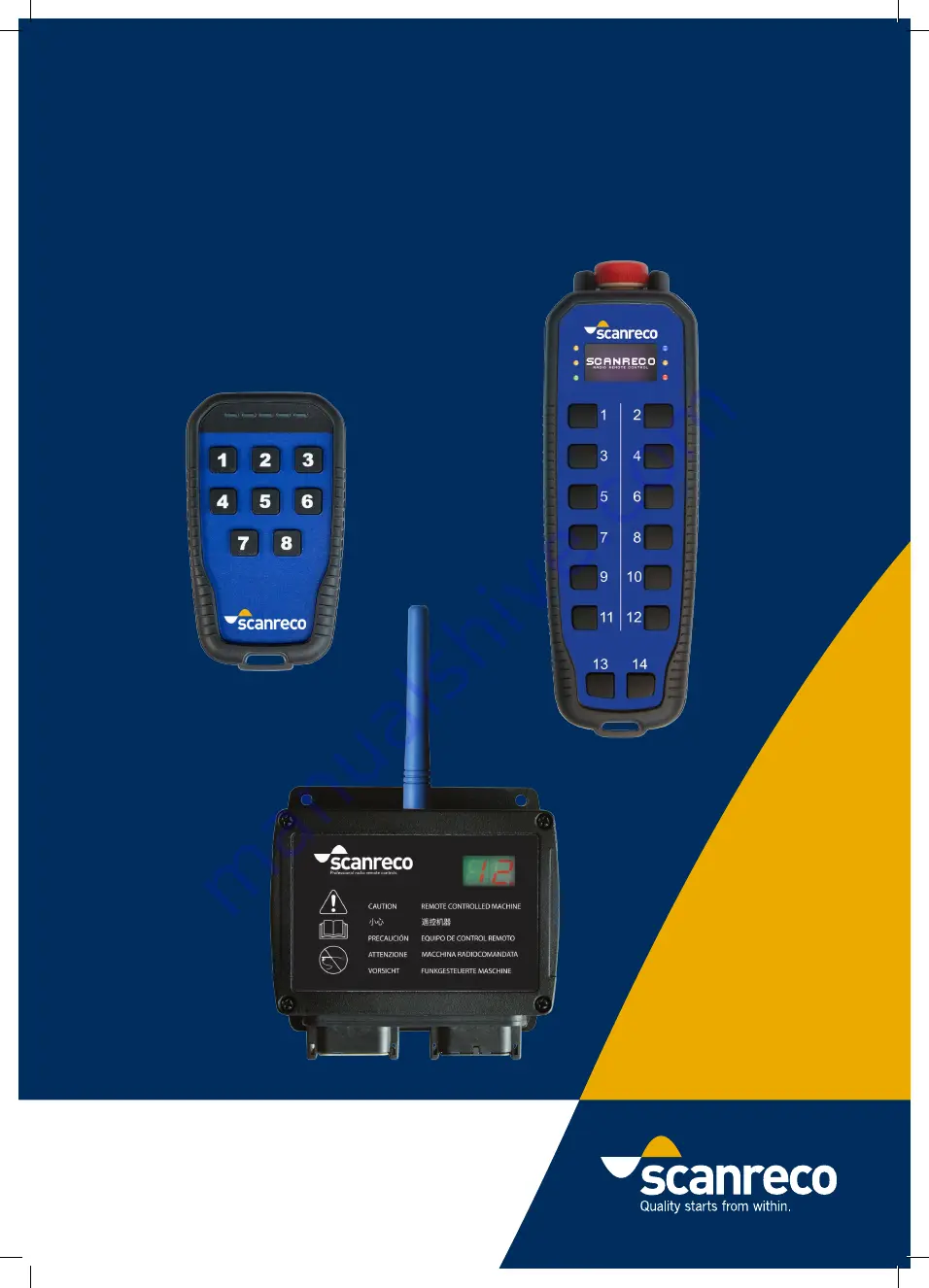
Страница 7: ... system is highly resistant against electromagnetic and radio frequency radiation The G5 system is comprised of a Pocket or Rocket Flex Transmitter with pushbuttons The Receiver provides the connection points for connecting to the electro hydraulic valves or controller Digitally coded control information is sent in both directions via radio between the Transmitter and the Receiver 3 System informa...
Страница 8: ... status feedback The buttons and the LED s can be configured for a variety of different operations The unit is powered with 3 standard AAA batteries and the backside has a belt clip for convenient attachment on the operator s belt 4 G5 Pocket Transmitter LED 1 Button 1 Button 4 Button 3 Button 6 Button 2 Button 5 Button 7 Button 8 LED 2 LED 3 LED 4 LED 5 Belt clip Battery compartment Belt clip rem...
Страница 9: ...e configured prior to operation The pushbuttons are easily programmed to activate any output or function Button definitions include momentary interlocked or latched output Please have a look at chapter 15 if any description of the functionality is declared There are two ways of configuring the functionality With On Site programming or with WinSCI software Neither of them are described in this manu...
Страница 10: ...dirt dust to ensure no water can enter the unit 5 Insert new batteries mind the polarity 6 Reassemble the lid and the belt clip Tighten the screws according to chapter 8 3 38 8mm 75 2mm 38mm 1 5 in 27mm 115mm 4 5 in 67mm 2 6 in Attribute Information Housing material Plastic PC ABS IP class IP67 Ambient temperature 25 C to 70 C 15ºF to 160ºF Supply 3 x AAA battery Operating time Several months depe...
Страница 11: ...l as a charge indication LED A 128x64 pixel monochrome OLED display is optional The buttons and the LED s can be configured for a variety of different operations The unit is powered with three re chargeable AA batteries which is included separately in the delivery The associated battery charger is recommended to be used with the unit The backside has a belt clip for convenient attachment on the op...
Страница 12: ...a momentary activation of output 1 6 button 9 14 are not mapped to any output If any other functions are required they need to be configured prior to operation The pushbuttons are easily programmed to activate any output or function Button definitions include momentary interlocked or latched output Please have a look at chapter 15 if any description of the functionality is declared There are two w...
Страница 13: ...ns below 1 Remove the belt clip by unscrewing the top middle screws 2 Unscrew the four screws holding the lid 3 Remove the batteries 4 Remove all dirt dust to ensure no water can enter the unit 5 Insert new batteries mind the polarity 6 Reattach the lid and the belt clip Tighten the screws 0 8 Nm IMPORTANT If using standard non rechargeable batteries do not use the charger 0 8 Nm 1 2 3 13 33 ...
Страница 14: ...Supply 3 x AA battery Operating time Without display up to 120 hours of operation With display up to 40 hours of operation depending on usage of LED and display Weight 400g 0 88lb including battery ISO 13849 for stop function Category 3 PL d 48mm 1 9 in 42mm 1 7 in 213mm 8 4 in 35mm 1 4 in 84mm 3 3 in 5 5 Technical data 14 33 ...
Страница 15: ...45 C 41 F to 113 F Dimensions 70 x 35 5 x 113 mm 2 75 x 1 4 x 4 45 in Weight 70 g 0 2 lbs 5 6 Battery charger The battery charger also works as a holder for the Rocket Flex The charger can be assembled on the machine with a 1 4 UNC screw same as RAM Mount Size B holders While the Rocket Flex is charging the blue LED is flashing When charging is finished the blue LED is lit The charger is delivered...
Страница 16: ...inputs and Deutsch connectors relay outputs with spring terminal block or CAN Bus output Since the Receiver can be exposed to very tough environments the box is encapsulated to give protection from damp heat cold dust vibration and corrosive environments The Receiver has short circuit proof inputs and outputs and has protection against polarity reverse over voltage large incoming voltage transient...
Страница 17: ...ifferent versions The main difference between the version types is the output type which can be either MOSFET output Relay output or CAN Bus output Versions with MOSFET output have two 12 pin Deutsch connectors while versions with relay output have cable glands with spring terminal block The CAN version have cables with M12 connectors The G5 system is required to be configured prior to operation r...
Страница 18: ...r Supply 9 36 VDC IP Class IP67 Connector Interface 2 x 12 pin Deutsch connectors Programming interface RS232 Overload Protection Yes maximum 36 VDC Current consumption 30 mA idle 60 mA External loads in operation Digital Inputs 14 can also be used as digital outputs Do not exceed supply voltage Digital Outputs 19 MOSFET driven outputs Short circuit proof overload protected E Stop Output Active wh...
Страница 19: ...mally open B13 REL10 common B14 REL10 normally closed B15 REL10 normally open 17 1 1 15 Attribute Information Power Supply 9 36 VDC IP Class IP65 Connector Interface Spring terminal block tool free assembly Programming interface RS232 Overload Protection Yes maximum 36 VDC Current consumption 30 mA idle 60 mA External loads in operation Digital Outputs 5 or 10 digital outputs Each output relay nee...
Страница 20: ...ower supply Once radio link is established Loop Out goes high Short circuit proof Max 2 7 Ampere load CAN bus CAN Open Ambient Temperature 25 C to 70 C 15 F to 160 F Weight 1 2 Kg 2 6 lbs Connection Pin no Colour Function 1 Brown Not used 2 White Power supply 12 24VDC 3 Blue GND CAN_GND 4 Black CAN_HIGH 5 Grey CAN_LOW Connection Pin no Colour Function 1 Brown Not used 2 White GND 3 Blue RS 232 TX ...
Страница 21: ...127mm 5 0in 57mm 2 2in 8 13mm 186mm 7 3in 117mm 4 6in 6 7 Receiver dimensions 157mm 6 18in 110mm 4 33in 140mm 5 51in 21 33 ...
Страница 22: ...s likely to cause harmful interference in which case the user will be required to correct the interference at his own expense This device complies with Industry Canada licence exempt RSS standard s Operation is subject to the following two conditions 1 this device may not cause interference and 2 this device must accept any interference including interference that may cause undesired operation of ...
Страница 23: ...pped with Deutsch connectors require M4 screws in the two lower holes The Receiver should be installed vertically or horizontally with with antenna facing upwards or horizontally The Receiver should never be assembled with cable glands connectors facing upwards or where it is exposed to accumulation of water moisture and other debris Engineering note Receivers equipped with Deutsch connectors requ...
Страница 24: ...etal object and should not be mounted in an area that is surrounded by metal as it causes reflections that significantly reduce range Keep the antenna at a distance of at least 10 cm from metal objects if possible Optimal range is achieved if the Transmitter and antenna are within line of sight Important during welding During electrical welding on machine all connectors from the Receiver must be d...
Страница 25: ...0 8 Nm 8 3 Torque values 0 8 Nm 0 8 Nm 0 5 Nm 1 5 Nm 25 33 ...
Страница 26: ...n and turn off buttons please refer to the programming section The LED display on the Receiver is used to indicate radio link or output activation The list below describes the different indications 9 Startup and LED indication G5 Receiver Meaning G5 Receiver CAN Link is established Standby Output 1 Activated Output 2 Activated Output 3 Activated Output 4 Activated Output 5 Activated Output 6 Activ...
Страница 27: ...g is performed during low battery on the Transmitter it may look like the paring works but it does not This is related to a safety precaution Replace battery and repeat the paring procedure A Remove power from Receiver unplug the Grey connector for G5 24 and remove the cover E The Transmitter will confirm the download is complete by flashing LED 3 eight times E G Turn off the power to the Receiver...
Страница 28: ... interruption or electrical disturbances Check that the connector pins and the terminal block connections in the Receiver are covered with grease suitable for electronic applications The grease will prevent oxidation of the connectors caused by water humidity and will increase the life span of the unit We recommend GreaseWay SG 32 W grease IMPORTANT Store the unit where it is safe It is the operat...
Страница 29: ...upply is connected check power supply Some buttons on the Transmitter do not work Button is not connected to any output Check if buttons are operational by following the instruction in chapter 12 3 Contact machine installer how to connect a button to an output Display on Receiver showing Po 00 or Po Id Jumper inside is set to Configuration mode or Pairing mode set both the jumpers to the Jumper re...
Страница 30: ...all buttons one at a time to ensure they function correctly Firmware and serial number will be shown in the display Pressing any two buttons at a time will illuminate LED 5 This ensures the red LED is functioning correctly Releasing the red stop button will illuminate LED 4 Pushing the red stop button will darken LED 4 Transmitter may restart during the stop button release The Transmitter will aut...
Страница 31: ...airing plug for G5 CAN 52019 Belt clip Pocket incl screws 52018 Lid for battery Pocket incl screws 51162 Belt clip Rocket Flex incl screws 51161 Lid for battery Rocket Flex incl screws 1 1 3 2 4 6 13 1 List of spare parts IMPORTANT Use only spare parts manufactured by SCANRECO for the specific product usage of spare parts manufactured by others may cause product damage and will void the warranty 1...
Страница 32: ...crimp pins 50265 Cable kit for G5 with Deutsch connectors 3 24 m cable 50258 Cable kit for G5 R5 R10 3 24 m power cable 0 55m Hirshmann cable 51070 Charger Rocket Flex incl cable 49587 Pouch for Rocket Flex excl waist belt 49812 Pouch for Rocket Flex incl waist belt 50763 Pouch for Pocket 1 3 2 4 5 6 6 7 14 Accessories 32 33 ...
Страница 33: ...available for system installer to provide final information to the operator on the programmed assignments 15 Programmed assignment template Input Output Interlock bank On delay ms Off delay ms Logic Rule Button 1 Button 2 Button 3 Button 4 Button 5 Button 6 Button 7 Button 8 Button 9 Button 10 Button 11 Button 12 Button 13 Button 14 Linked DF35 33 33 ...
Страница 34: ......