Quanta series
– Hardware Manual
QUANTAHM.1.2
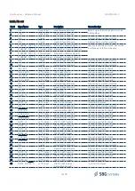
Pin #
Signal Name
Type
Description
Connection tips
37
SYNC_IN_D
LVTTL Input
Synchronization Input D
Leave unconnected if not used.
38
SYNC_IN_E/ODO_B
LVTTL Input
Synchronization Input E Odometer B
Channel
Leave unconnected if not used.
39
GND
Ground
Signal Voltage Reference
All ground pins must be connected.
40
GND
Ground
Signal Voltage Reference
All ground pins must be connected.
Note: All Synchronization inputs and outputs, as well as odometer input pins have inverted polarity when
compared to the firmware documentation and web page configuration. The “Rising edge” configuration
in the web page / firmware will be in fact triggered on the falling edge at hardware level. This is because
these inputs and outputs have been optimized for direct interfacing to a RS-232 receiver or driver, which
can enable robust and safe connection to remote equipment.
An external inverting buffer can also be used to maintain LVTTL levels while putting back the signals to
the same polarity as the firmware.
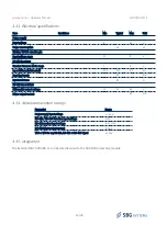
3.3.1.2. Electrical specifications
Item
Conditions
Min
Typical
Max
Unit
Power supply
Input voltage range
4.75
5
5.25
V
Power consumption
Quanta with Internal IMU
3.5
W
Quanta Extra
6
W
TTL Input pins
Input range
5V tolerant LVTTL
0
3.3
5
V
Low level threshold
0.8
V
High level threshold
2.0
V
Input current
40
µA
TTL output pins
Low level voltage
0
0.4
V
High level voltage
2.8
3.3
V
Max output current
20
mA
17/48

