Quanta series
– Hardware Manual
QUANTAHM.1.2
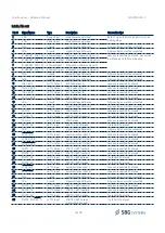
3.3.1.1. Pin out
Pin #
Signal Name
Type
Description
Connection tips
1
VDD
Power Input
Main Power Supply Input
Both VCC pins (Pin#1 and Pin#2) must be
tied together.
2
VDD
Power Input
Main Power Supply Input
3
GND
Ground
Signal Voltage Reference
All ground pins must be connected.
4
GND
Ground
Signal Voltage Reference
All ground pins must be connected.
5
ETHERNET_ Ethernet Input
Ethernet Port Receive Signal (+)
Leave unconnected if not used. See section
3.4.3 Ethernet interface otherwise.
6
ETHERNET_ Ethernet Output Ethernet Port Transmit Signal (+)
7
ETHERNET_PORT_RX- Ethernet Input
Ethernet Port Receive Signal (-)
8
ETHERNET_PORT_TX- Ethernet Output Ethernet Port Transmit Signal (-)
9
GND
Ground
Signal Voltage Reference
All ground pins must be connected.
10
GND
Ground
Signal Voltage Reference
All ground pins must be connected.
11
INS_LED_A
LVTTL Output
INS Led Output A
Leave unconnected if not used.
12
GNSS_LED_A
LVTTL Output
GNSS Led Output A
Leave unconnected if not used.
13
INS_LED_B
LVTTL Output
INS Led Output B
Leave unconnected if not used.
14
GNSS_LED_B
LVTTL Output
GNSS Led Output B
Leave unconnected if not used.
15
GND
Ground
Signal Voltage Reference
All ground pins must be connected.
16
GND
Ground
Signal Voltage Reference
All ground pins must be connected.
17
CAN_TX
LVTTL Output
CAN Transmit
Leave unconnected if not used.
18
PORTA_TX
LVTTL Output
PORT A UART Transmit
Leave unconnected if not used.
19
CAN_RX
LVTTL Input
CAN Receive
Leave unconnected if not used.
20
PORTA_RX
LVTTL Input
PORT A UART Receive
Tie to GND if not used.
21
GND
Ground
Signal Voltage Reference
All ground pins must be connected.
22
SYNC_IN_A
LVTTL Input
Synchronization Input A
Leave unconnected if not used.
23
SYNC_OUT_B
LVTTL Output
Synchronization Output B
Leave unconnected if not used.
24
SYNC_OUT_A
LVTTL Output
Synchronization Output A
Leave unconnected if not used.
25
PORTC_TX
LVTTL Output
PORT C UART Transmit
Leave unconnected if not used.
26
PORTB_TX
LVTTL Output
PORT B UART Transmit
Leave unconnected if not used.
27
PORTC_RX
LVTTL Input
PORT C UART Receive
Tie to GND if not used.
28
PORTB_RX
LVTTL Input
PORT B UART Receive
Tie to GND if not used.
29
SYNC_IN_C
LVTTL Input
Synchronization Input C
Leave unconnected if not used.
30
SYNC_IN_B
LVTTL Input
Synchronization Input B
Leave unconnected if not used.
31
GND
Ground
Signal Voltage Reference
All ground pins must be connected.
32
GND
Ground
Signal Voltage Reference
All ground pins must be connected.
33
PORTD_TX
LVTTL Output
PORT D UART Transmit
Leave unconnected if not used.
34
PORTE_TX
LVTTL Output
PORT E UART Transmit
Leave unconnected if not used.
35
PORTD_RX
LVTTL Input
PORT D UART Receive
Tie to GND if not used.
36
PORTE_RX/ODO_A
LVTTL Input
PORT E UART Receive /
Odometer A Channel
Tie to GND if not used.
16/48

