Navsight Solution
– Hardware Manual
NAVSIGHTHM.1.5
5.8. Serial ports interfaces
Serial port interfaces can be used to connect various external equipment and share very similar features and
capabilities. Specificity of different ports is detailed in the following sections. Some of the common
features are listed below:
●
4 800 to 921 600bps operation (Default set to 115 200)
●
RS-232 or RS-422 modes available for most interfaces, configured by software
●
Parity control enabling/disabling (disabled by default)
●
Data bits: 8
●
Stop bits: 1
●
1 x 12V power supply for external signal translation circuitry or powering external equipment (e.g.
odometer, radio modem, conversion to TTL or RS-422). Max 3W total power supply for all ports.
●
1 x Event/Sync input associated with each port
Note: Navsight automatically limits the serial signals slew-rate to minimize EMI and reduce
communication error when the baud rate is below 230 400 bps.
5.8.1. PORT A Interface
Although the PORT A shares most of the other serial ports characteristics, it has also some specific
features:
●
Fixed RS-232 communications
●
Dedicated interface for configuration over serial using sbgECom protocol
●
1 x SYNC OUT A (RS-232 level)
5.8.1.1. SYNC Out A functionality
The Sync OUT A can be configured in two ways:
●
Main loop divider: This event is activated at the sensor sample time, but its frequency is divided by
the output divider. If the divider is set to 4, pulse output frequency will be 200 Hz / 4 = 50 Hz.
●
PPS: This simple output is synchronized with each top of UTC seconds. Validity should be checked by
parsing the UTC messages status.
●
Virtual odometer. This output generates a pulse each X meters of travel, depending on user
configuration.
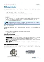
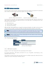
5.8.1.2. Connector specifications (rugged)
The PORT A connector uses an 8 ways female ODU connector (ref G81F1C-P08LFG00000). Other
manufacturers such as Fischer provide compatible plugs (Fischer Core Series).The connector mates with
plug ref S31F1C-P08MFG0-5500.
39/73
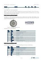
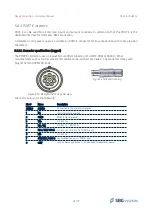
Figure 5.9: Receptacle front panel view
Figure 5.10: External plug


