background image

TRA 410, 421

9/19

P100015830 B

Connection diagrams

Connection diagrams

TRA410F210

TRA410F212

2 pt

NTC

230 V

230 V

L

N

1

2

1

2

1

2

1

2

a

b

c

d

2 pt

NTC

24 V

LS

LS

MM

1

2

1

2

1

2

1

2

a

b

c

d

TRA421F210

TRA421F212

2 pt

NTC

230 V

L

L

CO

N

NTC 22k

out

N

230 V

1

2

1

2

1

2

1

2

a

b

c

d

2 pt

NTC

24 V

LS

LS

CO MM NTC 22k

out

MM

1

2

1

2

1

2

1

2

a

b

c

d

Содержание TRA 410

Страница 1: ...ECC room thermostat TRA 410 TRA 421 Technical manual...

Страница 2: ...2 19 TRA 410 421 P100015830 B...

Страница 3: ...Liability limitation 6 2 3 Intended use 6 3 Setting the setpoint temperature 7 4 Functions settings parameterisation 8 5 Connection diagrams 9 6 Dimension drawing 10 7 Overview of display 11 8 Descrip...

Страница 4: ...4 19 TRA 410 421 P100015830 B...

Страница 5: ...l when it is dis connected from the power supply Only use the device when it is in a technically perfect condition Adhere to the ambient conditions specified in the fitting instructions 1 1 Meaning of...

Страница 6: ...ctions Failure to observe the operating instructions Improper usage Use of untrained staff Unauthorised modifications Technical changes In all other cases the obligations agreed to in the supply contr...

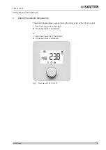
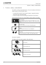
Страница 7: ...the setpoint temperature The setpoint temperature is set by turning the rotary knob to the left or the right 1 Turn the rotary knob to the LEFT The temperature is decreased Or 1 Turn the rotary knob t...

Страница 8: ...ple operation and settings Standard display In the standard display all room temperature controllers show the current actual temperature and the active functions The TRA421 also has a clock function O...

Страница 9: ...TRA410F210 TRA410F212 2 pt NTC 230 V 230 V L N 1 2 1 2 1 2 1 2 a b c d 2 pt NTC 24 V LS LS MM 1 2 1 2 1 2 1 2 a b c d TRA421F210 TRA421F212 2 pt NTC 230 V L L CO N NTC 22k out N 230 V 1 2 1 2 1 2 1 2...

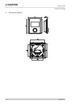
Страница 10: ...10 19 P100015830 B TRA 410 421 Dimension drawing 6 Dimension drawing...

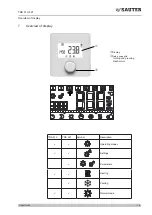
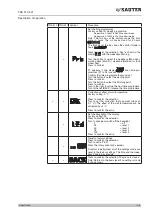
Страница 11: ...0 B Overview of display 7 Overview of display 1 2 1Display 2Rotary knob with turning and pressing mechanism TRA 410 TRA 421 Symbol Description P P Operating modes P P Settings P Parameters P P Heating...

Страница 12: ...ale for time pro gramme one unit one hour P P Current temperature setpoint temperature P P C Correction of effect of wall temperature P P Celsius temperature unit P Fahrenheit temperature unit P P Min...

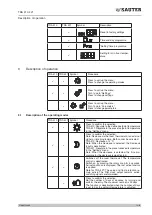
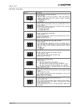
Страница 13: ...nfirm the selection Note Decrease via the room thermostat or an external signal or time programme Both cannot be activated TRA 410 Decrease of 2 C Note When the decrease is selected the Decrease input...

Страница 14: ...rm the entry P Set the setback temperature in the Cooling ECO mode Factory setting 23 C Press to confirm the selection Turn to set the setpoint temperature that you want Press to confirm the entry P S...

Страница 15: ...he button to select the finishing point Press to confirm Turn to the right to call up the next time programme Turn to the left BACK to leave the time programme P P Correction of effect of wall tempera...

Страница 16: ...k is activated and the operating mode is set to cooling the heating mode is also inactive Protects the locking of the operation with a code Factory setting 0 0 deactivated 1 activated Note The locking...

Страница 17: ...ling mode is initiated in good time ahead of the de fined time 0 deactivated 1 activated Set the cycle time for the valve protection facility Factory setting 14 days Prevents the plug from sticking in...

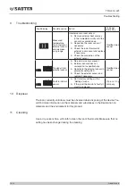
Страница 18: ...f f No external sensor present f f External sensor does not correspond to specifications f f Deactivate the external sensor in parameter setting 040 f f Check the external sensor and replace if necess...

Страница 19: ...Fr Sauter AG Im Surinam 55 CH 4016 Basel Tel 41 61 695 55 55 Fax 41 61 695 55 10 www sauter controls com info sauter controls com Printed in Switzerland...

Отзывы: