background image

 
Planning, transport, installation


LASERTEC 40


Page 54 


Electrical connection 


Risk of accident

 due electrical power! 


The electrical connection is only allowed to be made by an electrician.


The locally applicable regulations and directives are to be observed 
as a matter of priority. 


During work on electrical equipment, electronic components may be 
damaged by incorrect or faulty connection. 


It is imperative the information in the circuit diagrams is followed! 


Supply cable, fuse protection


The supply and fuse protection are to be designed as per the information 
on the rating plate for the switch cabinet. 


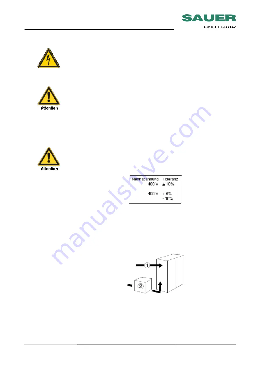
The actual mains voltage is not allowed to vary from the nominal voltage 
by more than the permitted tolerance even under load. 


 Connection


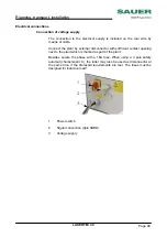
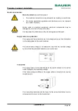
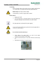
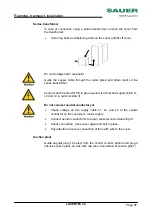
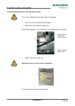
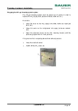
The supply cable is connected directly to the switch cabinet (1) to suit the 
mains voltage for the operating voltage. 


If the mains voltage is different, the supply cable is connected via a series 
transformer (2). 


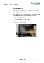
The connecting terminals and the fuses for the series transformer can be 
accessed via the cover on the transformer. 

Содержание LASERTECH 40

Страница 1: ...LASERTEC 40 Planning documentation LASERTEC 40 Documentation for preparatory measures for installation commissioning and operation including transport and installation instructions...

Страница 2: ...d to reproduce or copy using electronic data processing systems any part of this manual in any form including for training or educational purposes without the written approval of the publisher The ver...

Страница 3: ...ven for a short time Read the general health and safety regulations published by the related authorities If the regulations are not hung on the notice board in your organisation ask the responsible sa...

Страница 4: ...cturer Otherwise SAUER will accept no liability whatsoever for any damage or malfunctions that may occur Effective utilisation of the machine Training courses SAUER provides training and further train...

Страница 5: ...c instructions requirements and actions that are not allowed to prevent damage Please pay attention to the related information Also pass on all warnings and safety instructions to other operators Dang...

Страница 6: ...nger Please pay attention to the related information Take particular care in these cases to prevent placing people at risk due to electrical power Also pass on all safety instructions to other operato...

Страница 7: ...e transported to the installation location The machine is to be placed on levelling elements E P connection Connection of machine The machine is to be connected electrically clockwise rotating field T...

Страница 8: ...LMW 188 A the operating organisation undertakes the obligation to provide technical support during installation and repair work in particular the provision of suitable ladders platforms scaffolding h...

Страница 9: ...cation If problems should arise later due to failure to follow the information provided SAUER cannot be held responsible Ambient temperature The room must be evenly heated and the temperature should f...

Страница 10: ...n A suitable bearing plate approved by a structural engineer is required The bearing plate must not have any expansion joints in the area covered by the machine Cracks cable ducts or other interruptio...

Страница 11: ...intermediate storey including its substructure is adequate also in older buildings That the building regulations are met Note that the centre of gravity moves due to the weight of the workpieces and...

Страница 12: ...a binding manner as per DIN 4024 part 1 Flexible structures that support machines with rotating elements That the load bearing structure is able to absorb the actions of the machine s inertial forces...

Страница 13: ...for moving the machine to its installation location Room height Ensure the room height is adequate so that installation and maintenance work can be performed unhindered Machine area Ensure there are...

Страница 14: ...lds installation in potentially explosive atmospheres or areas containing potentially explosive substances consult SAUER GmbH Information for machines with series transformer The cable connection betw...

Страница 15: ...tallation LASERTEC 40 Page 14 Installation dimensions Height Machine height mm 2 370 inch 93 30 Transport height mm 2 300 inch 90 55 Width Machine width mm 2 476 inch 97 50 Length Machine length mm 2...

Страница 16: ...ion LASERTEC 40 Page 15 Installation area L x W mm 4 250 x 3 876 inch 167 32 x 152 60 E Mains connection In addition escape routes and safety areas are to be maintained in accordance with local laws r...

Страница 17: ...Planning transport installation LASERTEC 40 Page 16 Machine Standard...

Страница 18: ...ight Machine weight Machine Approx kg 2 200 Installation weight Machine with max weight for workpiece oils and liquids Max kg 2 250 Load of foundation plates KN 2 250 Machine supports Quantity type 3...

Страница 19: ...C due to EMC measures it must have a fixed connection In addition one of the measures stated below must be taken according to EN 50178 point 5 3 2 1 old VDE 0160 point 5 5 3 4 1 and 5 5 3 4 2 Earth co...

Страница 20: ...nductor PE Mains connection 3N PE 50 60 Hz 400 230 V Open cable length above floor m 0 8 Connecting cable cross section accd to DIN 5710 VDE 0100 Due to energy return and possible operation for short...

Страница 21: ...en by our customer service Transport safety During the transport of the machine there is a risk of accident due to material fracture tipping slipping or the machine falling Follow transport instructio...

Страница 22: ...tion feature Fit lifting irons in the recesses in the machine base if necessary Risk of accident due to pallet or crate falling or tipping Ensure the crate is straight Avoid tipping excessively on lif...

Страница 23: ...can be installed and connected immediately on delivery The data given in these instructions apply to the machine chip tray chip conveyor and series transformer For transport information and installati...

Страница 24: ...r the machine Either on a pallet with Plastic or aluminium poly cover within Germany Aluminium sheeting across Europe In a crate Accessories Standard accessories tools and documentation are packed wit...

Страница 25: ...transport damage Check machine and accessories for transport damage and for completeness using the delivery note In case of damage Report damage directly to SAUER service and in good time to the freig...

Страница 26: ...packaging if possible It is imperative you observe the markings and instructions on the packaging Take into account the related transport weight and the transport dimensions see shipping paperwork and...

Страница 27: ...is straight Pay attention to the markings for the centre of gravity so that the machine always hangs straight Pay attention to the markings for the attachment of tackle Avoid tipping excessively on li...

Страница 28: ...for transporting the machine without packaging transport device no 240663 On fitting and removing transport equipment it is imperative to ensure the measuring systems are not damaged Switch cabinet Th...

Страница 29: ...heral equipment Have any damage recorded on the shipping paperwork delivery note by the freight haulier If possible take photographs of the damage Inform SAUER service about the damage Remove the fast...

Страница 30: ...x kg 4 210 Exhaust system Approx kg 82 Chiller Approx kg 185 Transport dimensions approx L x W x H Machine ca m 2 30 x 1 40 x 1 95 Exhaust system ca m 0 66 x 0 36 x 1 38 Chiller ca m 0 85 x 0 55 x 1 0...

Страница 31: ...rcumstances lift support or push using delicate parts such as the control panel levers trim panels or splash protection feature Fit lifting irons in the recesses in the machine base if necessary Note...

Страница 32: ...on the right on the nuts with washers keep distance between laser and plate Mounten the nuts and tighten them Risk of accidents due to material breakage Hang crane hook into transport device Risk of...

Страница 33: ...the machine to the installation location and set down without shocks Risk of accident due to the machine dropping or falling as well as due to unauthorised access to the machine Never stand under sus...

Страница 34: ...e bottom lock nut Unscrew the threaded rod Re assemble the machine elements which were removed for the transport The transport devices are included in the scope of delivery of the machine and are requ...

Страница 35: ...the safety distance to people not directly involved in the transport is 1 5 times the height of the item lifted The systems necessary for the transport are only allowed to be used at fixed points on t...

Страница 36: ...ng roller transport systems i e max height of steel rollers When working with the systems necessary for lifting the machine the machine is to be appropriately secured against sudden lowering and slidi...

Страница 37: ...t the weight of the accessories included and the packaging Preparing Carefully prepare the machine for transport see Transport preparations Place the machine on an adequately large and strong pallet s...

Страница 38: ...s e g using moisture absorbing agent corrosion protection greases covers etc Marking packaging Attach appropriate information about the centre of gravity the attachment of tackle etc to the packaging...

Страница 39: ...the necessary space connections and tools on site Installation assembly connection and commissioning can also be undertaken by our customer service Stability Ensure machine and accessories are standin...

Страница 40: ...are to be followed during the installation of machines and switch cabinets e g in Germany Health and safety at work act VDE accident prevention regulations etc Maintain the stipulated safety areas and...

Страница 41: ...installation elements Position of the fastening points Type and number of levelling elements Installation dimensions fastening bolts Delivery ex works In case of delivery by SAUER the installation ele...

Страница 42: ...machine alternative 1 Fasten machine supports 9 using threaded rod 2 conical washer plate 8 spherical washer 7 conical washer 6 spherical washer 5 washer 4 and nut 3 in recess 1 on the machine base F...

Страница 43: ...ith fastened threaded rods 2 conical washer plate 8 and spherical washer 7 as per machine supports diagram See chapter Technical Data section Machine supports diagram Set down machine on the machine s...

Страница 44: ...work table or on the headstock Ensure measuring surface is clean Briefly push spirit level back and forwards on the measuring surface after fitting Check for changes and take the average value Exactly...

Страница 45: ...rt during installation and repair work in particular the provision of suitable ladders platforms scaffolding heavy tools lifting gear etc Assembly connection and commissioning can be undertaken by our...

Страница 46: ...chine parts such as guides stop surfaces bolted and clamping surfaces Use suitable solvent or cleaning agent Damage to lacquer by solvents Do not use aggressive solvents No trichloroethyline or simila...

Страница 47: ...irflow impedes the designed cooling capacity Positioning The free standing cooling plant must be placed on a horizontal surface Install the plant at a minimum distance of 30 cm from other objects in o...

Страница 48: ...aser BLUE 2 Water return line from laser RED Install cooling water inlet and outlet below the service door and connect to the water air cooler 1 Power switch 2 Serial data cable 3 Water feeder to lase...

Страница 49: ...y external disconnector with sufficient contact opening next to the plant which is marked as part of the plant Besides secure the phase with a 16A fuse When using a 3 pole safety automat characteristi...

Страница 50: ...oning of Cooling Plant Switch on the power switch The indication of the cooling control shows OFF Press the Standby key The display indicates the actual temperature and failure messages Water level an...

Страница 51: ...transportation of the sensitive components Furthermore the packing must provide a protection of the cooling plant from dust and soiling Pack the cooling plant in such manner to prevent it from shocks...

Страница 52: ...ASERTEC 40 Page 51 Connection of Cooling Plant Special option Water water cooler Guide fresh water inlet and outlet from underneath into the control cubicle and connect it to the planned places See al...

Страница 53: ...e right side of the machine Install the machine such that the switch cabinet is easily accessible Ensure that the switch cabinet cooling is not impaired Connection The connections between the machine...

Страница 54: ...age 53 Connection of Suction Plant Connect suction hose lead out underneath the service door from the machine and plug into the suction plant either on the long or the short side Connect electrical ca...

Страница 55: ...uit diagrams is followed Supply cable fuse protection The supply and fuse protection are to be designed as per the information on the rating plate for the switch cabinet The actual mains voltage is no...

Страница 56: ...e supply cable or connecting cable from the series transformer though the cable gland and strain relief on the switch cabinet PG cable glands are not included in the items supplied Connect earth condu...

Страница 57: ...or PE to green yellow terminal and supply cable L1 L2 and L3 to terminal strip X1 Do not connect neutral conductor yet Check voltage on the supply cable L1 L2 and L3 to the neutral conductor on the cu...

Страница 58: ...g a meter for Correct voltage Correct frequency Clockwise rotating field Correct connection of the neutral conductor in the customer s supply If all connections are correct close the switch cabinet On...

Страница 59: ...nge 6 16 bar Typical operating pressure and consumption 15 bar and 550 l min approx 35m h Connection to standard compressed air supply NW 7 2 Coupling DL plug NW7 2 1 2 AG Ident No 2470209 The custome...

Страница 60: ...eliver liquid fase are allowed for the operation e g rising pipe bottle rising pipe bottle set tank etc The supply pressure must be of min 55 bar For the connection to the customer s CO2 supply system...

Страница 61: ...e completed Open the valve for compressed air supply Open the valve at the CO2 supply unit Both pressure gauges 1 must show the corresponding system pressure Switch on the CO2 cooler 2 Switch the cool...

Страница 62: ...ressure bottles bottle set etc Procedure Close the valve on the CO2 supply unit bottle bottle set liquid gas tank etc Close the valve on the compressed air supply in house network etc Open the solenoi...

Страница 63: ...tions and protected against damage Supply cable connecting cable and earth conductor are correctly connected in accordance with regulations to series transformer and terminal strip X1 in the switch ca...

Страница 64: ...areas are met as per applicable regulations Machine is stable and positioned and installed as per the applicable regulations Electrical connection is fully checked and also all points in the check lis...

Страница 65: ...n feature are free of leaks Clamping fastening and connecting bolts are tightened Documentation safety instructions machine manuals control system manuals circuit diagrams etc is available Documentati...

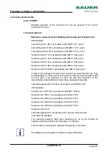
Страница 66: ...Lubricants Only the use of suitable lubricants provides a safe machine operation For spindle nuts and guides of X Y and Z axes use only the following lubricants Klueber Isoflex NBU 15 ident no 270517...

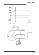
Страница 67: ...Planning transport installation LASERTEC 40 Page 66 Lubrication schedule...

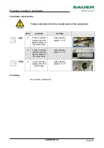
Страница 68: ...peripherals Item Location Activity 0 X axis 2 grease nipples second grease nipple on the other side apply grease approx 3 cm3 0 Y axis 2 grease nipples second grease nipple on the other side apply gr...

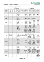
Страница 69: ...If water in the hydraulic oil cannot be excluded so called HLP D oils may be advantageous These oils must meet the minimum requirements in DIN 51 524 part 2 for hydraulic oil HLP 46 with the exception...

Страница 70: ...22 AVIA FLUID RSL22 AVILUB Hydraulic DD 22 AVIA FLUID HLP D 46 AVIA FLUID RSL 46 AVILUB Hydraulic DD 46 BP Energol RC R 46 BP Energol HLP 46 Energol GR XP 68 Energol HLP HM 10 BP Energol HLP D 22 BP...

Страница 71: ...M 68 68 Kl ber Kl beroil GEM 1 46 MOTOREX LAMORA HLP 46 COREX HLP D 68 RHENUS Hydranor HLP 10 Hydranor HLP 22 Hydranor HLP D 22 Hydranor HLP 46 Hydranor HLP D 46 Shell Morlina 150 Tellus Oel 46 Tellus...

Страница 72: ...PLEX 2 RHENUS Norlith MZP 2 Norplex LKR 2 Shell Alvania EP grease 2 Zeller Gmelin Divinol grease EP 2 Divinol Lithogrease 000 Coolant Supplier Description BASF Glysantin G 48 Protect Plus Central lubr...

Отзывы: