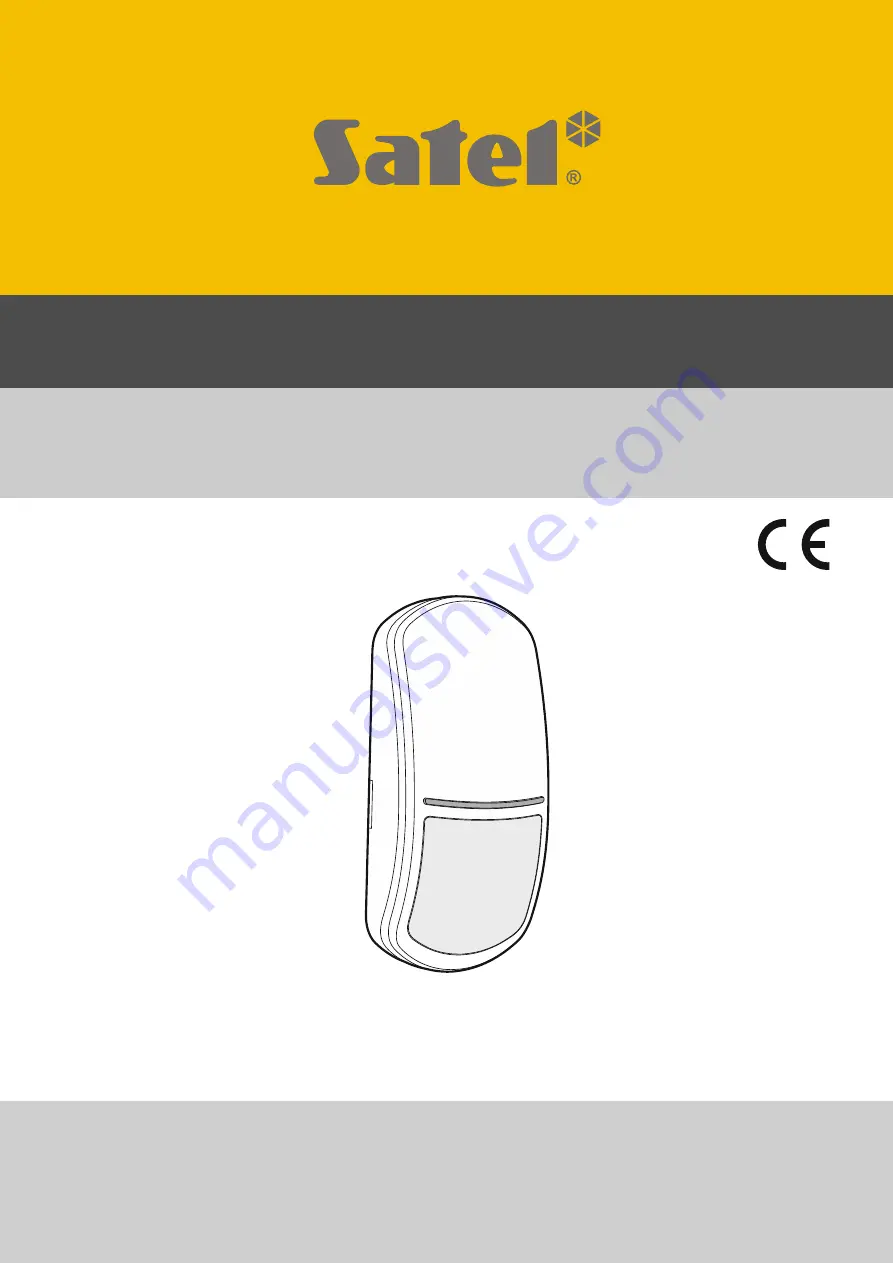
SLIM-PIR-PET
Digital passive infrared detector
with pet immunity up to 20 kg
Firmware version 1.00
slim-pir-pet_en 01/20
SATEL sp. z o.o.
• ul. Budowlanych 66 • 80-298 Gdańsk • POLAND
tel. +48 58 320 94 00
www.satel.eu
Страница 1: ...M PIR PET Digital passive infrared detector with pet immunity up to 20 kg Firmware version 1 00 slim pir pet_en 01 20 SATEL sp z o o ul Budowlanych 66 80 298 Gdańsk POLAND tel 48 58 320 94 00 www satel eu ...
Страница 2: ...ghts under the warranty SATEL aims to continually improve the quality of its products which may result in changes in their technical specifications and software Current information about the changes being introduced is available on our website Please visit us at http www satel eu The declaration of conformity may be consulted at www satel eu ce The following symbols may be used in this manual note...
Страница 3: ...res 2 2 Description 2 Supervision features 2 LED indicator 2 3 Electronics board 3 4 Selecting a mounting location 4 5 Installation 4 6 Configuring LED indicator settings 6 7 Start up and walk test 7 8 Specifications 7 ...
Страница 4: ...alarm output activation and the LED indicator coming on Signaling will continue as long as the trouble exists LED indicator The LED indicates warm up flashing green for about 30 seconds alarm ON for 2 seconds default color blue trouble steady ON for entire duration of the trouble the same color of lighting as in case of alarm You can change the color to be used to indicate alarm trouble see Config...
Страница 5: ...put pins for configuration of the detector outputs Available settings are shown in the figures 2 built in resistors are used connect the detector outputs as shown in Fig 9 3 built in resistors are not used connect the detector outputs as shown in Fig 8 pins to enable disable the LED indicator LED indicator potentiometer for adjustment of PIR sensor sensitivity fixing screw hole tamper switch PIR s...
Страница 6: ...ed on the bracket and must be installed at a height of 2 4 m with no inclination from the vertical 1 Remove the front cover Fig 4 2 Remove the electronics board Fig 5 3 Make the openings for screws Fig 6 and cable Fig 7 in the enclosure base 4 Pass the cable through the prepared opening 5 Secure the enclosure base to the wall Fig 6 The wall plugs anchors delivered with the device are intended for ...
Страница 7: ...SATEL SLIM PIR PET 5 ...
Страница 8: ...on mode The LED will start flashing in the color currently selected with the PIR potentiometer the color does not have to be the same as that used so far for alarm trouble indication by the LED 5 Use the PIR potentiometer to select a new color for alarm trouble indication 6 Put a jumper across the LED pins The settings will be saved The LED configuration mode will be terminated If you do not put a...
Страница 9: ...make the LED to turn on Figure 10 shows the maximum coverage area of a detector installed at a height of 2 4 m 8 Specifications Supply voltage 12 VDC 15 Standby current consumption 8 mA Maximum current consumption 23 mA EOL resistors 2 x 1 1 k Outputs alarm NC relay resistive load 40 mA 24 VDC tamper NC 100 mA 30 VDC Relay contact resistance alarm output 26 Ω Detectable speed 0 3 3 m s Alarm signa...
Страница 10: ...ade 2 Compliance with standards EN 50131 1 EN 50131 2 2 EN 50130 4 EN 50130 5 Environmental class according to EN 50130 5 II Operating temperature range 10 C 55 C Maximum humidity 93 3 Dimensions 62 x 137 x 42 mm Weight 100 g 5 year warranty from date of manufacture ...