background image


Satcube Ku User Manual v2.0-2019 


SATCUBE PROPRIETARY


Interface


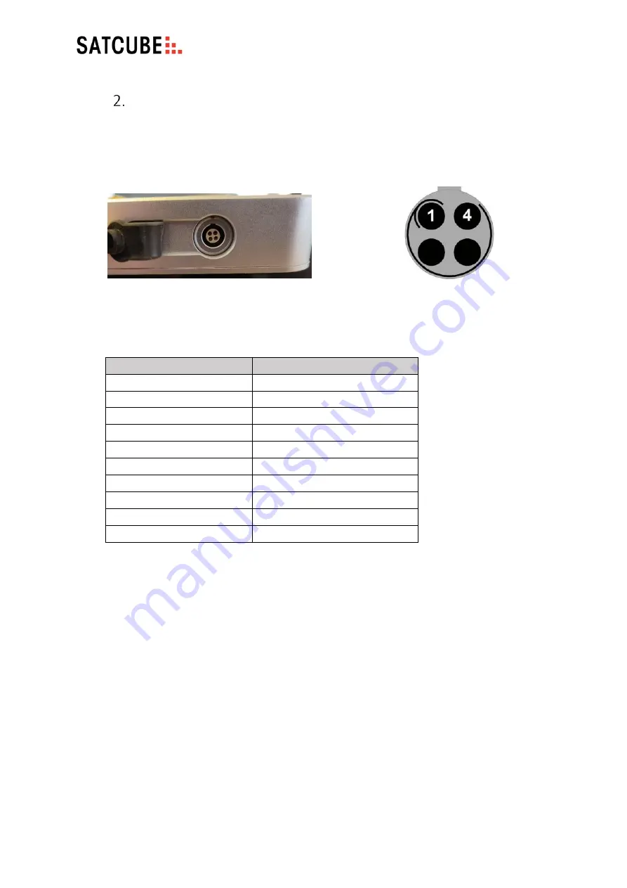
Power input 

The power input is located at the front right side of the terminal, covered by a rubber 
protection. 


Pins are rated for 7A each pin, 2+2 pins for DC power. Cable is equipped with a 16A fuse of 

GBC type, according to DIN 72581, size 25x6mm.  


Item 

Specification 

AC input range 

100 to 240 VAC, 47 

 63 Hz 

Power consumption 

Up to 150 W 

DC input voltage 

24 VDC 

DC connector type  

Circular push pull connector 

DC connector male type 

Crimp contact 

Current rating 

7+7 A* 

Pin count 

Max. operating temperature  + 120 °C 
Min. operating temperature  - 20 °C 
Connector IP grade 

IP 68 

Figure C2

 DC connector pin layout 

 (terminal view).   

Figure C1

 DC power input interface.  

Содержание Ku

Страница 1: ...Satcube Ku User Manual ...

Страница 2: ...n from the distributor before using the equipment This document is a user manual for the Satcube Ku terminal It is important to observe all safety and transmission requirements listed in this document and to operate the Satcube Ku according to the guidelines provided in this manual Any responsibility or liability for loss or damage in connection with the use of this product and the accompanying do...

Страница 3: ...s Keep the battery packs away from fire Do not disassemble break or otherwise tamper with the battery packs Do not drop the battery packs Do not expose the battery packs to temperatures above 50 C Only use Lithium Ion battery packs that are supplied by Satcube In case of battery fault contact Satcube support at www satcube com customer service ...

Страница 4: ...rity notice 8 b Environmental limitations 8 c Electricity precautions 9 d Operational precautions 10 a Deploy terminal 11 b Deploy front support 11 c Deploy antenna 11 d Power on 12 a Pointing Screen 13 b Status Bar 14 c Home Screen Information Screen 14 d Terminal Navigation 15 e Button functionality 15 a Profile selection 16 b Terminal geolocation 16 c Accessing the modem s GUI to configure down...

Страница 5: ...sion Criteria 19 e Prepare for Transmission 20 f Start transmission 20 a Enabling WIFI and changing the password via the GUI 22 b Connecting to Internet 22 a End transmission 22 b Power off 22 c Stow the terminal 23 a General guidelines 23 b Cleaning the fans 23 c Cleaning the protective vents 24 d Cleaning the moving mechanical parts 24 e Cleaning the interfaces and connections 25 f Storage instr...

Страница 6: ...tcube Ku User Manual v2 0 2019 SATCUBE PROPRIETARY Integrated Modem 41 OpenAMIP 43 Embedded Network Topology 44 General terminal specifications 37 Interface 38 Battery pack 40 UHP 210 41 iDirect IQ200 42 ...

Страница 7: ...ipe cooling system positioning system and all necessary user interfaces graphical and connections in one compact package This quick start guide is intended to help the operator with setting up and operating the terminal Troubleshooting and safety instructions are provided in order to aid the operator in safely handling and maintaining the terminal Contents and equipment list Table 1 Equipment list...

Страница 8: ...erated at wind speeds greater than 18 m s or 40mph The highest risk for the terminal to flip over is when the wind comes straight from behind the transmission direction and the antenna is at an upright position Temperature limitations The Satcube Ku terminal has an operating temperature range of 20 C to 50 C To avoid risk of high temperatures please avoid placing the terminal in direct sunlight ex...

Страница 9: ...away from live circuits To avoid injuries always disconnect power and discharge circuits before touching them User must not remove equipment covers or tamper with electric circuits in any way Figure 1 Ingress Protection IP rating explanation chart The Satcube Ku Terminal is rated IP65 ...

Страница 10: ...pplied antenna Radiation exposure is calculated with respect to the supplied manufacturer antenna Keep a safety distance from the signal aperture At all times make sure that an area within a safety distance of the terminal is cleared before starting transmission to avoid radiation damages The required safety distance depends on the antenna elevational angle the height of personnel possible bystand...

Страница 11: ...reaches its limit as in Figure 3 c Deploy antenna Release the latch on the front of the terminal according to Figure 4 To unfold the antenna simply hold the edge and lift it up 30cm 1 foot The antenna is deployed and secured with the adjustment wheels on each side of the front support Viewed from the rear of the terminal the wheel lock is on the left hand side of the terminal The lock is released ...

Страница 12: ...t battery will show a charging symbol if a battery is connected in this slot as illustrated in Figure 10 Figure 5 Wheel located on left hand side of terminal To LOCK UNLOCK turn as shown Figure 6 Lock on right hand side of the terminal To SECURE in position pull the lever as shown Locked position in the right picture Figure 7 Connection ports are located on the front of the terminal The DC power c...

Страница 13: ...the Ethernet ports on the front left hand side of terminal shown in Figure 7 Check the terminals assigned IP This is done by looking at the home screen on the display seen in Figure 17 where the IP address is visible Open a browser and type in the IP address found on the home screen as the URL This will display the GUI STATUS page Terminal Display Introduction and Navigation The terminal display c...

Страница 14: ...n the modem An arrow going from terminal towards globe means that transmission has been started If the globe turns green the terminal has established a connection to internet through the built in cloud check The different figures are shown in Figure 14 In the last box of the status bar in the bottom right the terminal transmission status is shown In Figure 11 the default status transmission turned...

Страница 15: ... to Home screen Information screen o Click the home button blue house or right arrow Click left arrow to return to pointing screen e Button functionality Buttons described below can be seen in Figure 18 White Cog Long press turns on off transmission Blue House Brings user to home screen C Long press turns terminal on and off Short press clears pointing data OK Long press initiate beam switching pr...

Страница 16: ...igure 33 b Terminal geolocation The terminal will use its built in GPS to automatically acquire its coordinates If the coordinates are not updated automatically open the GUI go to SETTINGS then scroll down to POSITION Tick the MANUAL SETTING checkbox and enter the terminal s latitude and longitude in the selected format decimal or deg min sec as seen in Figure 34 Press SAVE to apply the settings c...

Страница 17: ... terminal has restarted f Cloud Check Cloud check is a feature where the terminal tries to connect to a Satcube server to verify the satellite link s internet connection This info is then passed down to the user on the display as a pop up It also changes the globe icon on the display in order to indicate the terminal is connected to internet During the connection to the server information if a new...

Страница 18: ...inal On rough surfaces lift the terminal slightly before rotating ELEVATION use the adjustment wheel on the right hand side of the terminal Large adjustments can be made by manually raising the antenna as with initial deployment see section 4 To fine tune the elevation angle either lightly tighten the lock on the left side or pull the lever on the right side seen in section 4 c then use the right ...

Страница 19: ...levation will change unless the surface is completely flat Due to most surfaces are not perfectly flat or level this has to be done in order to point the terminal correct If the previous steps were done properly the signal strength is now maximized and the terminal is ready for transmission Troubleshooting If the C N value is zero for every position during the sweep above do one of the following i...

Страница 20: ...ning average e Prepare for Transmission Before starting the transmission make sure the area in front of the terminal is clear to avoid radiation damage Follow the safety instructions described in chapter 3 System safety When transmission is turned on a hazard symbol is shown in the display the hazard symbol can also be seen in Figure 22 f Start transmission i via the terminal controls Hold down th...

Страница 21: ...the current location either due to line of sight issues or wants to run the terminal on a different beam satellite a Beam switch can be requested from the modem Beam switch is initiated by a long press on the OK button and acknowledging the following pop up If the user has locked onto a carrier and starts the terminal transmit the acquisition timers starts the default for many systems it is set to...

Страница 22: ... through the built in hotspot A red cross through the WIFI icon means it is disabled It can be re enabled via the GUI shown in Figure 34 The ethernet LAN icon should always be shown and can be accessed through either one of the two ethernet LAN ports on the left front side of the terminal If the WIFI icon and Ethernet LAN icon are alternating flashing the WIFI module has not yet started End transm...

Страница 23: ...is found it should be reported immediately to Satcube support A faulty terminal may cause harm to humans and other equipment and should not be used During cleaning and maintenance the terminal should be inspected for damages or faults If any harm has come to the terminal please check in with Satcube support to assess if proper and safe handling of the terminal is still possible Every use Make sure...

Страница 24: ...r axis as seen in Figure 28 If the vents are not properly cleaned there is a possibility that pressure builds up which risks causing a malfunctioning terminal Note that no sharp object should be used to clean the protective vents as that might damage the vent or alter their functionality d Cleaning the moving mechanical parts The moving mechanical parts include o The elevation wheels o The elevati...

Страница 25: ...found If any dirt or other potentially harmful substances are present immediately clean affected interface Battery connections should be inspected to ensure no cleaning is needed f Storage instructions Before long time storage Batteries should be charged The terminal should be cleaned with a damp cloth to remove harmful substances The terminal should be stored in a dry place in temperatures within...

Страница 26: ...TINGS ABOUT Functions for each tab is provided below STATUS SYSTEM SATELLITE INFORMATION Information about what satellite profile is currently selected using either the GUI or terminal display TARGET Theoretical positioning angles for maximum signal strength Figure 29 Status screen as seen when logged into the terminal web GUI ...

Страница 27: ...GPS STATUS Whether coordinates have been entered manually and built in GPS is disconnected GPS SATELLITES Number of visible GPS satellites ACTIVE WARNINGS Indicates whether system is experiencing any errors GPS status monitors the built in GPS BUC LNB status monitors the uplink downlink Block UpConverter Low Noise Block downconverter CALENDAR displays current date and time TEMPERATURES Current tem...

Страница 28: ...urn the modem OFF in the case where an external modem should be used RECEIVE QUALITY LIMIT RQ Set the lower required limit to allow terminal transmission Used to make sure the terminal does not transmit unless pointed to a carrier Recommended value is 1 3 dB depending on satellite strength TX SYMBOL TX symbol in top right hand corner indicates when a transmission is active SETTINGS SATELLITE PRESE...

Страница 29: ... BUC is used in the transmit RF DETECTOR FREQUENCY A known carrier frequency to identify the selected satellite This is the L band frequency given in kHz RF DETECTOR GAIN Enter a value where the gain is increased if the selected carrier is weak RF DETECTOR BANDWIDTH Carrier bandwidth should be entered in kHz This enables the sensor to make a relative measurement of carrier strength to noise floor ...

Страница 30: ...ing SAVE WIFI i WIFI ON Tick the checkbox to turn WIFI ON This will be indicated on the terminal display ii SSID BROADCAST Tick the checkbox to make the terminal s WIFI network visible to external devices iii SSID The name of the WIFI network that will be broadcast to devices within range By default the name is MPACKWIFI We advise you to change this to enhance your security iv SECURITY Displays th...

Страница 31: ...he terminal Terminal is recommended to not use manual settings but to take an IP address from the modem This enables functionality otherwise not accessible as is described in Section 7 d IP ADDRESS Ip address of the Satcube terminal MASK Netmask assigned to the Satcube terminal GATEWAY The gateway that was assigned to the Satcube terminal DHCP ENABLE Enables a DHCP server on the Satcube terminal D...

Страница 32: ...ability to for the support to solve issues experienced CLOUD CHECK Enables the terminal to reach out to Satcube server to check for software updates help facilitate terminal support and if diagnostic data sharing has been enabled the terminal can give the user a notification when terminal connects to internet FANS Turn the fans ON OFF or activate AUTO mode fans will turn on automatically if the te...

Страница 33: ...ware revision and the serial number unique for each terminal SOFTWARE UPGRADE Allows a new software version to be installed Either upload a file from a local device and press INSTALL or with an active internet connection use the function CHECK ONLINE After Check online turns green the update can be initiated by clicking the Install button Figure 37 The ABOUT page of the GUI ...

Страница 34: ...ero offset for all angles IMU is not perfectly calibrated Disregard offset and align for the angles that maximizes the C N value Network icon and WIFI icon alternatively flash OR unable to find WIFI The WIFI module has not yet started If the problem continues for longer than 2 minutes after startup try restarting the terminal Alternatively try changing the WIFI name SSID by connecting external equ...

Страница 35: ...ing 3 Check line of sight 4 Check Magnetic Field value in GUI under status Typ 50 80μT if 100μTthere is most likely significant interference and changing terminal location is advised That allows for more accurate pointing values 5 Check correct GPS position is entered or has been found 6 UHP modem Check SNMP IP settings of modem 192 168 222 222 Should be set to Terminal IP 192 168 222 219 Polariza...

Страница 36: ...e or decrease elevation angle to an angle that is more than 12 degrees away from nominal elevation towards the current selected satellite Make sure the terminal is pointing towards open sky at this point Otherwise choose a different elevation azimuth location 2 Wait 3 seconds see the RQ value turn white If the value is not turning white make sure that the elevation angle is more than 12 degrees aw...

Страница 37: ...ppable batteries pack are optional Frequencies Tx 13 75 14 50 GHz Rx 10 95 12 75 GHz Polarization Linear Horizontal Vertical V H or H V EIRP Typical 46 dBW G T 9 dB K Satellite modem iDirect Evolution or UHP Networks Power consumption 130 W MAX Secondary links WLAN Interfaces 2 x LAN 1 x USB host WLAN Access Point IEEE 802 11 b g User interface Satcube GUI Display Pointing system Water and dust pr...

Страница 38: ...6A fuse of GBC type according to DIN 72581 size 25x6mm Item Specification AC input range 100 to 240 VAC 47 63 Hz Power consumption Up to 150 W DC input voltage 24 VDC DC connector type Circular push pull connector DC connector male type Crimp contact Current rating 7 7 A Pin count 4 Max operating temperature 120 C Min operating temperature 20 C Connector IP grade IP 68 Figure C2 DC connector pin l...

Страница 39: ... of 50 ohm One of which allows to connect to the transmit port of the BUC the Tx connector The second connector Rx connector allows the connection to the output of the LNB These can be used to connect external modems that works in the L band external signal generators or spectrum analyzers The connectors are protected behind a plastic cover fastened with two torx T10 screws Port Type 1 100 Mbps Et...

Страница 40: ...nstant current constant voltage Max charge voltage V 21V 4 2V Cell Max continuous charge current 4 0A Rec Charge cut off 100mA or timer 3 0h Max continuous discharge current 7 5A Rec discharge cut off 12 5V 2 5V Cell Internal impedance 200mΩ Cycle life After 250 cycles 60 of initial capacity Over charge detection 4 25V typical Over discharge detection 2 50V typical Discharge over current detection...

Страница 41: ...requencies in Ku band with associated symbol rate and roll off is configured into the profiles Listed below are some of the general settings that are essential for the modem to have to assure proper functionality in the Satcube terminal Local Oscillator values o These are set in the Site setup page that can be accessed in the left hand menu The Rx1 and Transmit values should correspond to LNB and ...

Страница 42: ...ilable LNB LOs 10 GHz 10 75 GHz 11 3 GHz Terminal available BUC LOs 12 8 GHz 13 05 GHz OpenAMIP set to communicate with 192 168 222 219 on port 5005 o For more information about OpenAMIP see Appendix E Management port IP address 192 168 222 222 29 DHCP enabled on the data port o This allows to disable manual IP settings in the terminal GUI and allows for smoother terminal configuration and adds cl...

Страница 43: ...t then only be accurately pointed to be able to start transmission in a new location Therefore using OpenAMIP reduces the amount of settings the remote terminal end user must configure considerably and allows for a much simpler terminal use To utilize OpenAMIP on a Satcube Terminal the following information should be configured to the modem in order to allow for the necessary information exchange ...

Страница 44: ...location of the different addresses can be found in Table 3 A network topology map can be found in Figure 38 All the switches are completely transparent to the network and allows all traffic VLAN traffic out from the modem must pass through ethernet port 2 as the WIFI module blocks VLAN tagged traffic Figure 38 Network topology map showing the embedded system with switches and interface ...

Страница 45: ...able for end user accessing the network 192 168 222 218 Unassigned Suitable for end user accessing the network 192 168 222 219 MCU Terminal User admin Default Password admin Alternative Password satcube123 192 168 222 220 MCU Antenna Reachable with added 8080 192 168 222 221 WiFi module 192 168 222 222 Modem IQ200 User admin Pass iDirect Pass2 P 55w0rd UHP Newtec No default pass 192 168 222 223 Br...

Отзывы: