background image

5

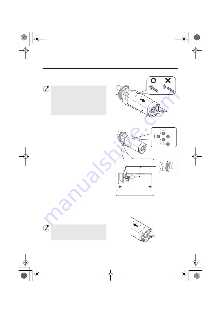
Checking the menus and zoom position using simple 
monitor output

1

Fully loosen the four cover fixing screws 
(A), and then pull the cover forward to 
remove it.

2

Use an alligator clip cable to connect the 
MONITOR pin on the circuit board at the 
bottom of the camera to the ground. 

A dedicated MONITOR connector (D) is 
provided for portable monitors.

1

Checking and changing the menu 
settings

2

Checking and changing the zoom 
position

• The optional camera control unit 

(VAC-70) can be used to perform same 
operations as the camera.

&

 See page 13.

3

Install the camera cover, and then 
tighten the four cover fixing screws (A) 
evenly.

• If only removing the camera cover 

(B)

partially loosen the cover fixing screws 

(A)

.

• If removing the lens cover 

(C)

 too, fully 

loosen the cover fixing screws 

(A)

.

The screw washers on the inside will 
come loose. Be careful not to lose 
them.

MONITOR

GND

D

In order to maintain waterproof 
performance, tighten the cover fixing 
screws to the following torques.

A:

 0.5 - 7 N·m (5 - 10 kgf·m)

(A)

B

C

A

L5CE2_US(INSTALLATION).book  5 ページ  2008年1月23日 水曜日 午後4時8分

Содержание VCC-XZ600N - Network Camera - Weatherproof

Страница 1: ...ation To User 1 Installation method 3 Checking the menus and zoom position using simple monitor output 5 Desiccant for preventing humidity 6 Connections 7 Features 11 How to Perform the Settings in the Menu Screens 13 Learning the Menu Setting Operations 14 Using the Electronic Manual CD ROM 16 Main specifications 17 Inserted at the end of this manual Pattern Sheet Accessories Dimensions Back page...

Страница 2: ... close to the ceiling in a kitchen or boiler room as the temperature may rise to high levels Cleaning Dirt can be removed from the cabinet by wiping it with a soft cloth To remove stains wipe with a soft cloth moistened with a soft detergent solution and wrung dry then dry by wiping with a soft cloth Do not use benzine thinner or other chemical products on the cabinet as this may cause deformation...

Страница 3: ...Consult the dealer or an experienced radio TV technician for help For the customers in Canada Underwriters Laboratories Inc UL has not tested the performance or reliability of the security or signaling aspects of this product UL has only tested for fire shock and or casualty hazards as outlined in UL s Standard for Safety for Commercial Closed Circuit Television Equipment UL 2044 Second Edition Da...

Страница 4: ...her side of the camera base should be 3 cm 1 2 in or more A A A B A C B A 1 1 2 Adjusting the camera position and angle Use the accessory hexagon wrench large to loosen the screws of the part you would like to move and then adjust so that the lens faces in the direction of monitoring within an angle of 45 degrees 1 If the camera is adjusted to an angle of 45 degrees or more the cables will become ...

Страница 5: ...ews C 2Move the sunshade adjustment mounting bracket A forward or back so that the accessory sunshade D can be installed and then tighten the accessory fixing screws C 3Align the sunshade D with the screw holes in the sunshade adjustment mounting bracket A and then install it by tightening the accessory sunshade fixing tapping screws E B A C When temporarily removing the fixing band after it has b...

Страница 6: ...ition The optional camera control unit VAC 70 can be used to perform same operations as the camera See page 13 3Install the camera cover and then tighten the four cover fixing screws A evenly If only removing the camera cover B partially loosen the cover fixing screws A If removing the lens cover C too fully loosen the cover fixing screws A The screw washers on the inside will come loose Be carefu...

Страница 7: ...hen remove the camera unit B from the camera fixing bracket C 3Replace the desiccant with the accessory desiccant 4Install the camera unit B as shown in the illustration and then align the camera fixing screw A with the screw hole D in the camera unit and tighten them 5Install the camera cover Refer to step 3 in Checking the menus and zoom position using simple monitor output P5 Be sure to observe...

Страница 8: ...ra to the LAN through a switching hub using shielded LAN cables Do not use the power supply of the camera Do not supply power to the PoE hub or PoE power adapter until the camera installation is finished MEMO You may extend the transmission distance by using multiple switching hubs with PoE support For details on the extendable distance please refer to the hub performance in the specifications etc...

Страница 9: ...router IP address on the LAN side Camera IP address default 192 168 0 2 Port number on the LAN side Camera video port number default 80 Port number on the WAN side Optional For communication use TCP IP When connecting to a router use the straight type LAN cable CAT5 or higher When connecting to an ADSL modem or other devices refer to the instruction manual for the device MEMO When viewing video in...

Страница 10: ...1U 7C 2V 600 m 656 yds max Note All connection cables should be 24 AWG or higher with a maximum length of no more than 600 m 656 yds Coaxial cable b With AC 24 V Power Supply Connection b With DC 12 V Check that polarity is correct For the connections use AWG 20 21 22 cables 1 Push and hold the lever a and then insert the cable into the terminal hole B 2 Release the lever A BNC type Digital video ...

Страница 11: ...R EXT ALARM 1 10 For details see Setting the Alarm Input ALARM IN in the electronic manual contained in the CD ROM b ALARM IN 1 1 is selected b ALARM IN 2 2 is selected Alarm input signal Alarm input signal Alarm Signal Input If a lamp is connected to this cable it will light up when an alarm signal is received or when the built in motion sensor detects movement Alarm Signal Output FOCUS ZOOM DC 6...

Страница 12: ...ablishing the network communication OPTION NETWORK b You can switch the viewing mode manually between the color mode and the black white mode CAMERA COLOR EXT ALARM Camera Title You can set and display the camera title This helps you confirm from which camera the image is sent when multiple cameras are connected Maximum 16 characters OPTION DISPLAY TITLE ROOM1 ROOM2 ROOM1 ROOM2 Alarm Notice b The ...

Страница 13: ...hat the white balance adjustment is properly configured CAMERA WHITE BALANCE ATW MASKING Backlight Compensation b The camera uses 48 part split metering areas to compensate the backlight condition by metering each area You can also select 5 part split metering areas center left right top and bottom for metering CAMERA BLC MULT or CENT b You can mask a metering area you do not want to meter CAMERA ...

Страница 14: ...nu 2 Moves the cursor during menu setting operations 3 Switches the menu screen 4 Performs focusing or zooming in out operations While the auto focus function is activated you can perform focusing operations using the buttons j NEAR l FAR d WIDE c TELE B Using the VAC 70 camera control unit optionally available to perform the settings remotely 1 3 2 4 1 2 4 3 VAC 70 BNC type Video in VIDEO OUT CAM...

Страница 15: ...ET SET SET SET SET SET OFF END Main menu Press and hold the button for about 3 seconds SYNC CAMERA LENS ALARM PRIVACY MASK PASSWORD LANGUAGE OPTION PRESET MENU y y y y y y y INT 1 SET SET SET SET SET SET OFF END Pressing the jl button moves the cursor Cursor Menu item 3 Select a setting value 4 Go to the next screen SYNC CAMERA LENS ALARM PRIVACY MASK PASSWORD LANGUAGE OPTION y y y y y y y INT 1 S...

Страница 16: ...utton Restoring all the default values on the camera In the main menu select ON for PRESET and press the SET button Note that the resetting operation does not reset the settings for the following items PRIVACY MASK on main menu PASSWORD on the main menu DISPLAY TITLE and SYSTEM on the OPTION menu Zoom or focus setting in POSITION on the CAMERA menu Note that the value of the item POSITION is reset...

Страница 17: ... screen click an item on which you want to get relevant information An applicable page will open Viewing menu setting procedures for each usage Click Guide to the Setting Menu on the menu located on the left of the screen Viewing definitions of glossary Click Glossary on the menu located on the left of the screen Viewing troubleshooting procedure Click Troubleshooting on the menu located on the le...

Страница 18: ...Network LAN terminal RJ 45 terminal 10 Base T 100 Base TX Operating ambient temperature humidity 10 50 C 14 122 F 90 RH max no condensation With power source connected 20 50 C 4 122 F Power source 24 V AC 10 60 Hz 12 15 V DC Supplied through PoE compliant with IEEE802 3af Power consumption 7 3 W Weight With sunshade Approx 2 0 kg 65 oz Without sunshade Approx 1 8 kg 58 oz Image compression JPEG H ...

Страница 19: ...es and other countries The official name for Windows used in this manual is Microsoft Windows Operating System In this manual note that the word Windows is used for referring to Microsoft Windows XP Operating System Intel and Pentium are registered trademarks or trademarks of Intel Corporation and its subsidiaries in the United States and other countries IBM and IBM PC AT are trademarks of Interna...

Страница 20: ...MEMO L5CE2_US INSTALLATION book 19 ページ 2008年1月23日 水曜日 午後4時8分 ...

Страница 21: ...ations pour l utilisateur 1 Méthode d installation 3 Vérification des menus et de la position de zoom avec une sortie d écran simple 5 Dessiccatif de prévention de l humidité 6 Branchements 7 Caractéristiques 11 Comment effectuer les réglages dans les écrans de menu 13 Apprentissage des opérations de réglage menu 14 Utilisation du manuel électronique CD ROM 16 Spécifications principales 17 Inclus ...

Страница 22: ...autres dommages Faites attention lors de l installation près du plafond dans une cuisine ou dans une chambre des machines car la température risque de monter à un niveau élevé Nettoyage La poussière peut être retirée du boîtier en l essuyant à l aide d un chiffon doux Pour retirer les taches essuyez à l aide d un chiffon doux humecté d une solution de détergent doux et bien essoré puis séchez à l ...

Страница 23: ...adio TV expérimenté pour obtenir de l aide Pour les clients situés au Canada Underwriters Laboratories Inc UL n a pas testé les performances ou la fiabilité pour ce qui concerne les aspects de sécurité ou de signalisation du présent produit UL a testé uniquement les risques d incendie de choc et ou d accidents comme indiqué dans le document édité par UL Standard for Safety for Commercial Closed Ci...

Страница 24: ...as de vis qui dépasse de l autre côté de l embase doit être longue d au moins 3 cm 1 2 po A A A B A C B A 1 1 2 Réglage de la position et de l angle de la caméra Utilisez la clé hexagonale fournie la grande pour desserrer les vis de la partie que vous désirez déplacer puis réglez les de manière à ce que l objectif fasse face à la zone de surveillance avec un angle de 45 degrés 1 Si la caméra est r...

Страница 25: ...ion fournies C 2Déplacez le support de fixation et de réglage du pare soleil A vers l avant ou l arrière pour pouvoir monter ce dernier D puis serrez les vis de fixation fournies C 3Alignez le pare soleil D aux trous de vis de son support de montage et de réglage A puis fixez le en serrant les vis autotaraudeuses de fixation du pare soleil E B A C Pour enlever le coller de serrage temporairement u...

Страница 26: ...écommande en option VAC 70 peut effectuer les mêmes opérations que la caméra voir page 13 3Montez le couvercle de la caméra en serrant ses quatre vis de fixation du couvercle A à fond Si vous ne désirez enlever que le couvercle de la caméra B ne desserrez les vis de fixation du couvercle A que partiellement Si vous désirez également enlever le cache de l objectif C desserrez entièrement les vis de...

Страница 27: ... de son support de fixation C 3Remplacez le dessiccatif par celui fourni 4Positionnez l unité de caméra B comme le montre la figure puis alignez la vis de fixation de la caméra A au trou de vis D à l intérieur de l unité serrez le tout 5Remontez le couvercle de la caméra Référez vous à l étape 3 de Vérification des menus et de la position de zoom avec une sortie d écran simple page 5 Assurez vous ...

Страница 28: ...és LAN N utilisez pas l alimentation de la caméra N alimentez pas le concentrateur ni l adaptateur de l alimentation PoE tant que l installation de la caméra n est pas terminée N B Vous pouvez étendre la distance de transmission en utilisant des concentrateurs de commutation multiples avec prise en charge de la fonction PoE Pour les détails sur la distance possible veuillez vous référer à la perfo...

Страница 29: ...rnant le routeur Adresse IP côté LAN Adresse IP de la caméra par défaut 192 168 0 2 Numéro de port côté LAN Numéro de port vidéo sur la caméra par défaut 80 Numéro de port côté WAN Optionnel Pour la communication utilisez TCP IP Pour la connexion à un routeur utilisez un câble LAN de type droit CAT5 ou supérieur Pour la connexion à un modem ADSL ou à d autres dispositifs reportez vous au manuel d ...

Страница 30: ...U 7C 2V 600 m 656 yd maxi Remarque Tous les câbles de branchement doivent être au moins 24 AWG et d une longueur maximale de 600 m 656 yd Câble coaxial b Avec CC 12 V Vérifiez si la polarité est correcte Pour les connexions utilisez des câbles AWG 20 21 22 b Avec CA 24 V 1 Poussez et maintenez le levier A puis introduisez le câble dans le trou de la borne B 3 Relâchez le levier A Connexion de l al...

Страница 31: ...vir de bornes pour la commutation entre le mode vidéo couleur et le mode vidéo noir et blanc au moyen d un interrupteur extérieur Assurez vous que l option COUL est sélectionnée 1 Borne ALARM IN 1 2 Borne ALARM IN 2 Pour tout détail consultez Réglage de l entrée d alarme ENT ALARME dans le manuel électronique contenu dans le CD ROM b ALARM IN 1 1 est sélectionné b ALARM IN 2 2 est sélectionné Alar...

Страница 32: ... à distance via une communication de réseau OPTION RESEAU b Vous pouvez commuter manuellement le mode de visualisation entre couleur et noir et blanc CAMERA COUL ALARME EXT Titre de la caméra Vous pouvez définir et visualiser le titre de caméra Lorsque plusieurs caméras sont connectées cela vous permet d identifier la caméra dont proviennent les images 16 caractères maximum OPTION AFFICHER TITRE R...

Страница 33: ... correctement CAMERA EQUIL BLANC ATW MASQUAGE Compensation de contre jour b La caméra utilise des zones de mesure divisées en 48 pour compenser le contre jour en mesurant chaque zone Vous pouvez également sélectionner des zones de mesure divisées en 5 centre gauche droite haut et bas pour effectuer la mesure CAMERA BLC MULT ou CENT b Vous pouvez masquer une zone de mesure que vous ne souhaitez pas...

Страница 34: ...glage menu 3 Commute l écran de menu 4 Effectue des opérations de mise au point ou zoom avant arrière Vous pouvez utiliser ces boutons pour effectuer la mise au point lorsque la fonction de mise au point automatique est activée j Proche l Éloignée d Grand angulaire c Téléobjectif B Avec la télécommande pour caméra VAC 70 disponible en option pour effectuer les réglages à distance 1 3 2 4 1 2 4 3 V...

Страница 35: ...R FIN Menu principal Appuyez et maintenez enfoncé le bouton pendant environ 3 secondes SYNC CAMERA LENTILLE ALARME MASQUE M PASSE LANGUE OPTION PREREGLAGE MENU y y y y y y y INT 1 REG REG REG REG REG REG ARR FIN Pressez le bouton jl pour déplacer le curseur Curseur Article de menu 3 Sélectionnez une valeur de réglage 4 Allez au menu suivant SYNC CAMERA LENTILLE ALARME MASQUE M PASSE LANGUE OPTION ...

Страница 36: ...enu principal sélectionnez MAR pour PREREGLAGE puis pressez le bouton SET Remarque elle ne réinitialise pas les réglages pour les articles suivants MASQUE dans le menu principal M PASSE dans le menu principal AFFICHER TITRE et RESEAU dans le menu OPTION Réglage du zoom ou de la mise au point dans POSITION dans le menu CAMERA Notez que la valeur de l article POSITION passe de MAR à la valeur par dé...

Страница 37: ...es informations appropriées Une page pertinente s affiche Visualisation des procédures de définition menu pour chaque utilisation Cliquez sur Guide au menu de réglage sur le menu situé à gauche de l écran Visualisation des définitions de glossaire Cliquez sur Glossaire sur le menu situé à gauche de l écran Visualisation de la procédure de résolution des problèmes Cliquez sur En cas de problème sur...

Страница 38: ...e d étanchéité IP66 Réseau Borne LAN borne RJ45 10 Base T 100 Base TX Humidité température ambiantes de service 10 50 C 14 F 122 F 90 RH maxi pas de condensation Avec alimentation connectée 20 50 C 4 F 122 F Source d alimentation CA 24 V 10 60 Hz CC 12 15 V Fourni à travers PoE conforme au IEEE802 3af Consommation d énergie 7 3 W Poids Avec pare soleil Env 2 0 kg 65 oz Sans pare soleil Env 1 8 kg ...

Страница 39: ...me Windows utilisé dans le présent manuel est la suivante système d exploitation Microsoft Windows Dans le présent manuel remarquez que le terme Windows se réfère au système d exploitation Microsoft Windows XP Intel et Pentium sont des marques déposées ou des marques commerciales d Intel Corporation et de ses filiales aux Etats Unis et dans d autres pays IBM et IBM PC AT sont des marques commercia...

Страница 40: ...N B L5CE2_US INSTALLATION book 19 ページ 2008年1月23日 水曜日 午後4時8分 ...

Страница 41: ...odo de instalación 3 Verificación de los menús y la posición de zoom usando una sencilla salida de monitoreo 5 Desecante para evitar la humedad 6 Conexiones 7 Características 11 Realización de los ajustes en las pantallas del menú 13 Aprendizaje de las operaciones de ajuste del menú 14 Uso del Manual Electrónico CD ROM 16 Especificaciones principales 17 Que se incluye en el final de este manual Pa...

Страница 42: ...lorar o dañar Tenga cuidado al instalarla cerca del techo en una cocina o una habitación con una caldera a combustión pues la temperatura podría subir a niveles altos Limpieza El polvo puede ser limpiado del exterior con un paño suave Para remover las manchas limpie con un paño suave mojado en una solución de detergente suave y retuérzalo para escurrirlo luego limpie con un paño suave y seco No us...

Страница 43: ...comerciante o a un técnico de radio y televisión experimentado para que le ayude Para los clientes en Canadá Underwriters Laboratories Inc UL no ha realizado pruebas de rendimiento o fiabilidad de las características de seguridad o de señalización de este producto UL ha realizado sólo pruebas de daños por fuego choque y o por accidentes como se establece en la normativa de UL Standard for Safety f...

Страница 44: ...tornillo se extiende del otro lado de la base de la cámara debe ser de 3 cm 1 2 pu o más A A A B A C B A 1 1 2 Ajuste de la posición y ángulo de la cámara Use la llave hexagonal accesoria grande para aflojar los tornillos de la parte que desea mover y luego ajuste de manera que la lente quede en la dirección de monitoreo dentro de un ángulo de 45 grados 1 Si la cámara se ajusta a un ángulo de 45 g...

Страница 45: ...a ménsula de montaje de ajuste de la visera A hacia adelante o atrás de manera que se pueda instalar la visera accesoria D y luego apriete los tornillos de fijación accesorios C 3Alinee la visera D con los agujeros de tornillos en la ménsula de montaje de ajuste de la visera A y luego instálela apretando los tornillos de fijación de la visera E B A C Al desmontar temporariamente la banda de fijaci...

Страница 46: ...la cámara opcional VAC 70 puede usarse para realizar las mismas operaciones que la cámara ver la página 13 3Instale la cubierta de la cámara y luego apriete los cuatro tornillos de fijación de la cubierta A parejamente Si sólo desmonta la cubierta de la cámara B afloje parcialmente los tornillos de fijación de la cubierta A Si también desmonta la cubierta de la lente C afloje completamente los tor...

Страница 47: ... de fijación de la cámara A y luego desmonte la cámara B de la ménsula de fijación de la cámara C 3Cambie el desecante por desecante de recambio 4Instale la cámara B tal como se indica en la figura y luego alinee el tornillo de fijación de la cámara A con el agujero de tornillo D en la cámara y apriétela 5Instale la cubierta de la cámara Consulte el paso 3 en Verificación de los menús y la posició...

Страница 48: ...és de un conmutador mediante cables LAN apantallados No utilizar la fuente de alimentación de la cámara No alimentar con energía el conmutador PoE o el adaptador de corriente PoE hasta no haber terminado con la instalación de la cámara NOTA Se puede ampliar la distancia de transmisión usando varios conmutadores compatibles con PoE Para mayor información acerca de la ampliación de distancia consult...

Страница 49: ...ma con respecto al enrutador Dirección IP de la LAN Dirección IP de la cámara predeterminado 192 168 0 2 Número del puerto de la LAN Número del puerto para vídeo de la cámara predeterminado 80 Número del puerto de la WAN Opcional Para la comunicación usar TCP IP Al conectarse a un enrutador usar el cable LAN recto CAT5 o superior Al conectarse a un módem ADSL u otros dispositivos consultar el manu...

Страница 50: ...das máx RG 11U 7C 2V 600 m 656 yardas máx Nota Todos los cables de conexión deben ser 24 AWG o mayores con un largo máximo de no más de 600 m 656 yardas Cable coaxial Conexión de alimentación b Con 12 V CC Comprobar que la polaridad es correcta Para las conexiones usar cables AWG 20 21 22 1 Empujar y sujetar la palanca A y a continuación insertar el cable en el orificio del terminal B 2 Soltar la ...

Страница 51: ...6V 12V Acercar Teleobjetivo Conexión para zoom enfoque Los terminales de entrada de alarmas pueden usarse además como terminales para cambiar entre los modos color y blanco y negro mediante un interruptor externo Comprobar que está seleccionado COLOR 1 Terminal ALARM IN 1 2 Terminal ALARM IN 2 Para mayor información consultar Ajuste de la entrada de alarmas ENTRADA ALARMA en el manual electrónico ...

Страница 52: ...do la comunicación de red OPCION RED b Es posible cambiar el modo de visualización manualmente entre el modo color y el modo blanco y negro CAMARA COLOR ALARMA EXTERNA Título de la cámara Es posible ajustar y visualizar el título de la cámara Esto ayuda a identificar cuál es la cámara que está enviando imágenes cuando hay varias cámaras conectadas Máximo 16 caracteres OPCION VISUALIZACION TITULO R...

Страница 53: ...ctamente CAMARA BALANCE BLANCO ATW MASCARA Compensación de la luz de fondo b La cámara usa áreas de medición divididas en 48 partes para compensar la luz de fondo midiendo cada área Es posible seleccionar también áreas divididas en 5 partes centro izquierda derecha parte arriba e abajo para la medición CAMARA BLC MULT o CENT b Es posible aplicar una máscara al área de medición que no se desea medi...

Страница 54: ...ciones de ajuste del menú 3 Cambia la pantalla del menú 4 Realiza la operaciones de enfoque y de acercamiento alejamiento Mientras está activada la función de enfoque automático es posible realizar las operaciones de enfoque usando los botones j Acercar l Alejar d Granangular c Teleobjetivo B Usando la unidad de control de la cámara VAC 70 disponible como opción para realizar los ajustes a distanc...

Страница 55: ...y y y y INT 1 AJU AJU AJU AJU AJU AJU OFF FIN Menú principal Pulsar y mantener pulsado el botón durante unos 3 segundos SINC CAMARA LENTE ALARMA MASCARA PRIV CONTRASENA IDIOMA OPCION PREAJUSTES MENU y y y y y y y INT 1 AJU AJU AJU AJU AJU AJU OFF FIN Si se pulsa el botón jl el cursor se desplaza Cursor Elemento del menú 3 Selección de un valor de ajuste 4 Ir a la pantalla siguiente SINC CAMARA LEN...

Страница 56: ...de la cámara En el menú principal seleccionar ON en PREAJUSTES y pulsar el botón SET Tener en cuenta que la operación de restablecimiento no restablece los ajustes de los siguientes elementos MASCARA PRIV del menú principal CONTRASENA del menú principal VISUALIZACION TITULO y RED del menú OPCION Ajuste de zoom o enfoque en POSICION del menú CAMARA Observar que el valor del elemento POSICION se res...

Страница 57: ...ea obtener mayor información Se abre una página pertinente Visualización del procedimiento de ajuste del menú para cada uso Hacer clic en Guía del menú de ajuste en el menú situado en el lado izquierdo de la pantalla Visualización de las definiciones de los glosario Hace clic en Glosario en el menú situado en el lado izquierdo de la pantalla Visualización del procedimiento de localización y soluci...

Страница 58: ... impermeabilidad IP66 Red Terminal LAN terminal RJ45 10 Base T 100 Base TX Temperatura humedad del entorno operativo de 10 a 50 C 14 a 122 F 90 HR máx sin condensación Con la fuente de alimentación conectada 20 a 50 C 4 a 122 F Fuente de alimentación 24 V CA 10 60 Hz 12 15 V CC Suministrada a través de PoE conforme a IEEE802 3af Consumo eléctrico 7 3 W Peso Sin parasol Aprox 2 0 kg 65 onzas Con pa...

Страница 59: ...marcas de Microsoft Corporation en los Estados Unidos y en otros países El nombre oficial para Windows usado en este manual es Microsoft Windows Operating System Notar que en este manual la palabra Windows se refiere al sistema operativo Microsoft Windows XP Intel y Pentium son marcas registradas o marcas de Intel Corporation y sus filiales en los Estados Unidos y en otros países IBM e IBM PC AT s...

Страница 60: ...NOTA L5CE2_US INSTALLATION book 19 ページ 2008年1月23日 水曜日 午後4時8分 ...

Страница 61: ...L5CE2_US INSTALLATION book 0 ページ 2008年1月23日 水曜日 午後4時8分 ...

Страница 62: ...172 6 8 150 5 9 141 5 7 110 4 4 4 8 5 0 3 Pattern sheet Scale 1 1 Unit mm inch L5CE2_US INSTALLATION book 1 ページ 2008年1月23日 水曜日 午後4時8分 ...

Страница 63: ...n et de réglage du pare soleil 1 7 Support de fixation 1 8 Vis de fixation 2 9 Connecteur une touche avec cordon de connexion 1 Le connecteur sert à relier les câbles d alimentation Ces câbles peuvent être retirés pour permettre la connexion d autres câbles si nécessaire F CD ROM VA SW3050Lite Plug in Manuel électronique 1 Accesorios 1 Visera 1 2 Tornillos de fijación de la visera 2 3 Banda de fij...

Страница 64: ...S SANYO Electric Co Ltd Printed in China Dimensions 400 16 381 15 182 7 2 29 1 2 87 3 4 87 3 4 29 1 2 141 5 7 172 6 8 75 3 0 123 4 9 224 8 9 211 8 3 21 0 9 113 4 5 Unit mm inch L5CE2_US INSTALLATION book 3 ページ 2008年1月23日 水曜日 午後4時8分 ...

Отзывы: