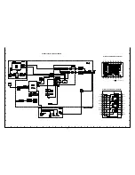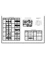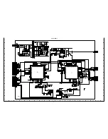
TV system :
PAL standard (625 TV lines, 25 frames/sec.)
Scanning system
: 625 TV lines, 50 field/sec., 2:1 interlace
Image device :
Interline transfer method, 1/3 inch solid state CCD
Picture elements :
795 (Horizontal) x 596 (Vertical)
Effective picture elements :
752 (Horizontal) x 582 (Vertical)
Synchronization system :
Internal sync.
Resolution :
480 TV lines horizontally, 400 TV lines vertically
Video output signal level :
1.0 Vp-p/75
Ω
(screw-on terminal)
S/N ratio :
More than 48 dB
Minimum required illumination :
1.8 lux (F 1.6 lens)
White balance :
A (Automatic: TTL system)/M (Manual) manual switching
Backlight compensation :
1 (On)/0 (Off) manual switching,
Active-zone light measuring system
Backlight compensation iris level adjustment :
Manual LEVEL volume control
Aperture :
1 (High)/0 (Normal) manual switching
Gain control :
Automatic
MONITOR output pin :
1.0 Vp-p/75
Ω
, test point pin
Lens :
F1.6 ~ 2.3, f=2.6 ~ 6.0 mm, varifocal lens, manual zoom and focus adjustment
Iris system :
Mechanical auto iris
Operational environmental conditions :
Temperature: -10
°
C ~ + 50
°
C
Humidity: less than 90 %
Storage environmental conditions :
Temperature: -20
°
C ~ + 60
°
C
Humidity: less than 70 %
Power supply :
12-15 V DC/ 24 V AC, 50 Hz
Power consumption
: 3.5 W
Weight :
Approx. 420 g
SERVICE MANUAL
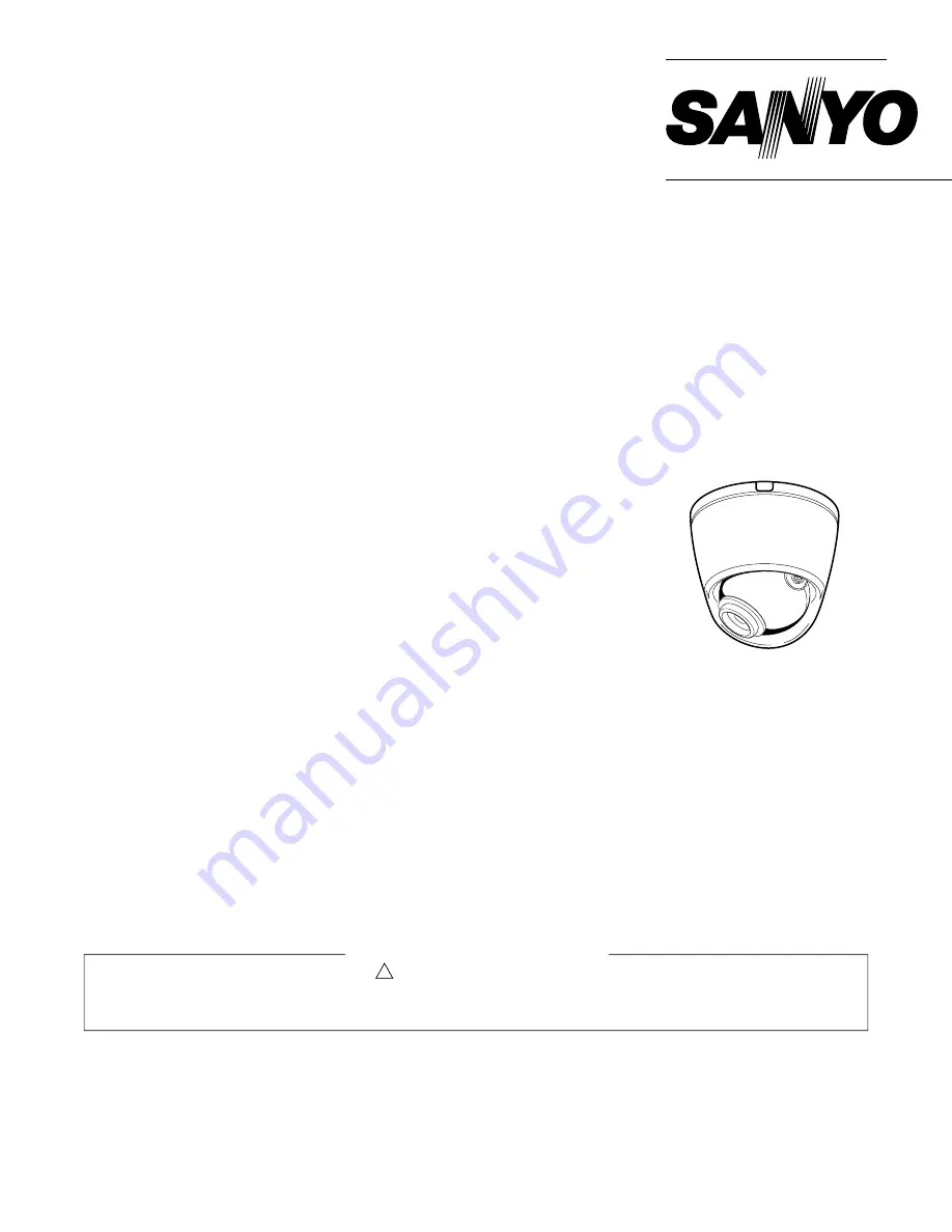
COLOUR CCD Camera
VCC-9615P
(Product Code : 117 047 15)
(Europe)
FILE NO.
REFERENCE No. SM5310516
L5AR2/XE
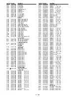
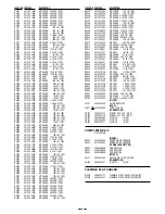
NOTE : 1. Parts order must contain model number, part number, and description.
2. Substitute parts may be supplied as the service parts.
3. N. S. P. : Not available as service parts.
Design and specification are subject to change without notice.
The components designated by a symbol ( ! ) in this schematic diagram designates components whose value are of
special significance to product safety. Should any component designated by a symbol need to be replaced, use only the
part designated in the Parts List. Do not deviate from the resistance, wattage, and voltage ratings shown.
PRODUCT SAFETY NOTICE
CONTENTS
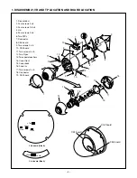
1. DISASSEMBLY, VR AND TP LOCATION
AND BOARD LOCATION .................... 2
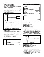
2. ADJUSTMENT ..................................... 3
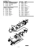
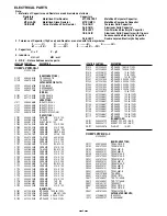
3. PARTS LIST ......................................... 5
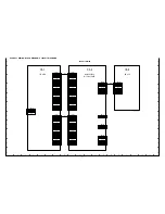
CIRCUIT DIAGRAM &
PRINTED WIRING BOARDS ................. C1
SPECIFICATIONS
Содержание VCC-9615P
Страница 23: ...Jun 03 SANYO Electric Co Ltd Osaka Japan ...


