INSTRUCTION MANUAL
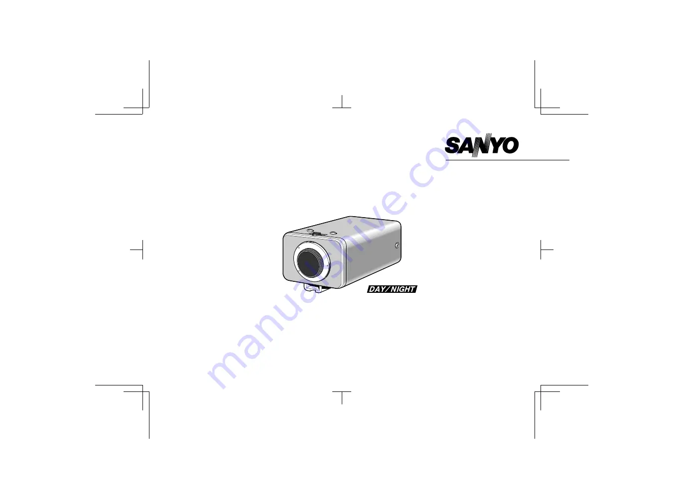
VCC-4374
COLOR CCD CAMERA
About this manual
Before installing and using the camera, please read this manualcarefully. Be sure to keep it handy for later reference.
L53U4/US GB 1999, 10, 14
Страница 1: ...NSTRUCTION MANUAL VCC 4374 COLOR CCD CAMERA About this manual Before installing and using the camera please read this manual carefully Be sure to keep it handy for later reference L53U4 US GB 1999 10 14 ...
Страница 2: ...oduct for repair or reinstallation of the product after repair This warranty does not apply to repairs or replacements necessitated by any cause beyond the control of SFC including but not limited to any malfunction defect or failure caused by or resulting from unauthorized service or parts improper maintenance operation contrary to furnished instructions shipping or transit accidents modification...
Страница 3: ...according to the subject brightness Built in interline transfer method 1 3 CCD approx 410 000 picture elements Low smear anti blooming low lag no burning and no geometric distortion using the CCD solid state image device 100 solid state components giving excellent immunity to shock and vibration Not subject to interference from magnetic or electrostatic fields High sensitivity minimum required ill...
Страница 4: ...sed in accordance with the instructions may cause harmful interference to radio communications However there is no guarantee that interference will not occur in a particular installation If this equipment does cause harmful interference to radio or television reception which can be determined by turning the equipment off and on the user is encouraged to try to correct the interference by one or mo...
Страница 5: ... audio speakers the magnetic field they generate will distort the image Protect from humidity and dust To prevent damages to the camera do not install it where there is greasy smoke or steam where the dampness may get too high or where there is a lot of dust Protect from high temperatures Do not install close to stoves or other heat generating devices such as spotlights etc or where it could be su...
Страница 6: ...lly when switching sources This rolling can be minimized by turning this volume 5 24 V AC input terminal 24 V AC GND 6 Camera setup section under the cover These settings are for when using a 1 3 inch CS mount DC without EE internal amplifier type lens However if due to installation conditions or environment the settings may need to be modified for best results see SETTINGS To access the controls ...
Страница 7: ...he bracket can be fixed at the top or bottom of the camera When fixing the bracket be sure to use the longer screws and install the shorter screws on the opposite side to seal the openings 1 Shorter screws M3 x 4 2 Longer screws M3 x 6 3 Camera mounting screw hole 1 4 20 UNC CAUTION When installing the camera support select a location that can support the total weight of the camera and accessories...
Страница 8: ...ilable on the lens for iris adjustments Set the A I LENS switch to the VIDEO position Compatible auto iris lenses 1 3 inch Sanyo DC type lens VIDEO type lens VCL CS8LY Standard angle f 8 mm Standard angle f 9 mm VCL CS4LY Wide angle f 4 mm Telephoto angle f 12 mm VCL CS2LY Ultra wide angle f 2 8 mm More telephoto angle f 16 mm If using a VIDEO type auto iris lens Set the ALC and LEVEL controls on ...
Страница 9: ...aximum telephoto position set the focus using the focus ring on the lens 3 Set the zoom lens to the maximum wide angle position set the focus using the flange back adjustment lever 4 Repeat steps 2 and 3 until the image stays in focus when changing from a telephoto shot to a wide angle shot When the setting is complete tighten the flange back lock screw Note When flange back lock screw is complete...
Страница 10: ... lens To allow for flange back adjustment install the supplied C mount adaptor on the lens mount then carefully align the lens mount with the camera opening and turn the lens slowly to install it 3 Connect the lens plug to the lens iris output connector LENS on the side of the camera When using lenses from other makers the plug shape may not correspond to the terminal on the camera In such a case ...
Страница 11: ...nstall the lens iris plug Solder the cable to the pins following the correct pin layout refer to the table and illustrations then close the plug cover Pin layout DC type lenses VIDEO type lenses 1 Brake coil 12 V DC 50 mA max 2 Brake coil Not used 3 Drive coil Video output 1 0 Vp p high impedance 4 Drive coil Ground for video signal and DC power 1 2 4 3 1 4 3 1 2 2 L53U4 US GB 1999 10 14 English 9...
Страница 12: ...y UL listed wire rated VW 1 should be used for the 24 V AC cable input terminal 3 Insert the plug of this power cord into a wall outlet The POWER indicator A will light Adjust the picture on the monitor using the Brightness and Contrast controls Coaxial cable type and maximum length Cable type RG 59U 3C 2V 250 m maximum Cable type RG 6U 5C 2V 500 m maximum Cable type RG 11U 7C 2V 600 m maximum CAU...
Страница 13: ...of the images when switched In such a case set as described below Switch the display on the monitor from camera 1 to camera 2 Adjust the LINE PHASE volume on camera 2 until the vertical roll of the image stops If more than two cameras are used please repeat this procedure for all the cameras CAUTION If the vertical roll cannot be corrected by setting the LINE PHASE volume on camera 2 try setting t...
Страница 14: ... the contrast If shooting simultaneously in a dark room and through a bright window If the subject background is extremely bright or dark If the brightness of the picture on the monitor is not correct Backlight compensation setting Use an auto iris lens and set the EI BLC switch to the BLC ON position to engage the backlight compensation function If using a VIDEO type auto iris lens The ALC volume...
Страница 15: ...r fluorescent light the image may flicker In such a case change to incandescent lighting or set the EI BLC switch to the OFF position and use an auto iris lens When shooting bright subjects pay attention to the light angle in order to avoid or minimize the smear phenomenon effect When using an auto iris lens for indoor outdoor use Set the EI BLC switch to the OFF position CAUTION If conditions are...
Страница 16: ...ter may switch from black and white to color mode Use only enough infrared lighting so that the mode is not switched The focus setting may be different in black and white mode and color mode Please check the focus setting in both modes Manual color black and white setting Connect each pin of the CONTROL terminal as indicated below to set the image to black and white or color as desired Color image...
Страница 17: ...e lens the LEVEL volume inside the camera casing should be adjusted B When using a VIDEO type lens the LEVEL volume on the lens should be adjusted The picture is not clear Is the monitor correctly adjusted Is the flange back position correctly set Is the lens focus correctly adjusted Are the lens surfaces clean If there is dust or finger prints on the lens the image quality will deteriorate To cle...
Страница 18: ...de Approx 1 4 lux with a F 1 2 lens color mode Control terminal Manual color black and white setting Backlight compensation Manual ON OFF switching Multi zone light measuring system Active when using an auto iris lens Iris function Manual ON OFF switching Electronic iris range 1 4 lux to 70 000 lux F 1 2 lens color mode 2 0 lux to 100 000 lux F 1 4 lens color mode Flange back 12 5 mm 0 5 mm White ...
Страница 19: ...SPECIFICATIONS Dimensions mm Features and specifications are subject to change without prior notice or obligations 136 126 5 1 15 4 25 2 11 1 4 20 UNC 67 54 28 3 L53U4 US GB 1999 10 14 English 17 ...