-10-
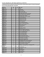
Service Adjustments with Replacing Memory IC(IC801)
No.
Item
Range
Data
Description
43
DOSD
0 ~ 1
1
Select Digital OSD mode/Analogue OSD mode
44
EXCNT
0 ~ F
8
Align Ext. RGB amplitude
45
OSDCN
0 ~ 7
2
Align OSD AC level
46
RGBSW
0 ~ 1
1
Select the temperature characteristics for RGB DC output
47
ACLDF
0 ~ 1
0
Disable Contrast ABL
48
ACLSW
0 ~ 1
0
Changes inclination of Contrast ABL
49
BABLD
0 ~ 1
0
Disable brightness ABL
50
MIDDF
0 ~ 1
0
Disable brightness mid stop
51
BABLT
0 ~ 7F
2
Align brightness ABL threshold
52
RGBT
0 ~ F
0
Select RGB DAC test mode
53
CLKSP
0 ~ 1
0
Test Mode
54
TSTMD
0 ~ 7
0
Test Mode
55
VXOAD
0 ~ 7
4
VXO Adj.
56
MCBCR
0 ~ 1
0
Chroma Test Mode
57
FODDS
0 ~ 1
0
Select DDS mode
58
CBCRI
0 ~ 1
0
Select YCbCr Input
59
CEXT
0 ~ 1
0
Selected of chroma signal
60
CBYPS
0 ~ 1
0*
Select chroma BPF bypass
61
CK ON
0 ~ 1
0
C Kill Mode (0: Enable Killer circuit)
62
CK OFF
0 ~ 1
0
Disable Killer circuit (for IC Test)
63
CKOPE
0 ~ 7
4
Select color killer operational level
64
AUTOG
0 ~ 7
0
Adjust Auto Green level
65
TINT
0 ~ 1
0
Set tint center value
66
WBADJ
0 ~ 1
0
Auto correct black level
67 IDKIL
0 ~ 7
4
Select color ident operational level
68
CVCOA
0 ~ 7
4
Control free Run frequency of chroma VCO
69
CVCOC
0 ~ 1
0
VCO free run mode
70
FSCSP
0 ~ 1
1
Select 10 pin output
71
COLSY
0 ~ 7
2*
Select Color System
72
RBGAI
0 ~ F
A
R-Y/B-Y Gain Balance
73
RBANG
0 ~ F
5
R-Y/B-Y Angle
74
RYLEF
0 ~ 1
D
R-Y DC Level (White-Balance)
75
BYLEF
0 ~ 1
E
B-Y DC level (White-Balance)
76
GYAMP
0 ~ F
6
Adjust G-Y amplitude
77
HTNCL
0 ~ 1
0
Select color on/off at Half Tone Mode
78
VXOFR
0 ~ 1
0
VXO test mode
79
VXOSB
0 ~ 1
0
VXO test mode
80
DEEMS
0 ~ 1
1
Select De-emphasis filter cut-off frequency
81
BELAD
0 ~ F
7
Align Bell filter
82
EQUAD
0 ~ F
0
Align Equalizer
83
BELMO
0 ~ 1
0
SECAM test mode
84
SKLOP
0 ~ 7
4
Select SECAM color killer operational level
85
SKLON
0 ~ 1
0
SECAM Color Kill Mode (0: Enable Killer Circuit)
86
SKLOF
0 ~ 1
0
Disable Killer circuit (for IC Test)
87
BELBY
0 ~ 1
0
Select BELL Filter bypass
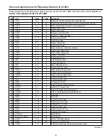
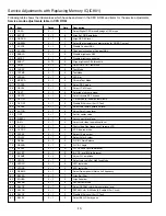
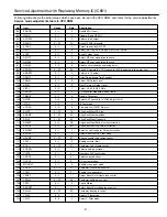
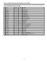
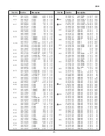
Following table shows the initial values which have been stored in the CPU ROM, and items for the service adjustments.
Service mode adjustments table in CPU ROM
SM_21-BE4B (FC8-A) IDN 6/24/08 10:53 AM Page 10


