background image

79 


Constant power control 

The following characteristics apply to UG-TB3, UG-TB3U, and UG-TB4. 

Specifications 


Condition 


Accuracy 

• Power supply voltage fluctuation 

• Load 

• Ambient temperature 

Rated voltage ± 10% 

Constant 

Constant 

±1% 

FS 

• Power supply voltage 

• Load fluctuation 

• Ambient temperature 

Constant 

4 times the rated load 

Constant 

±5% 

FS 

• Power supply voltage 

• Load 

• Ambient temperature fluctuation 

Constant 

Constant 

–10°C to +50°C 

±3% 

FS 


For conversion board patterns F and H, which do not use the external CT, the 

accuracy is ±5% FS under all the above conditions. 

Characteristics 


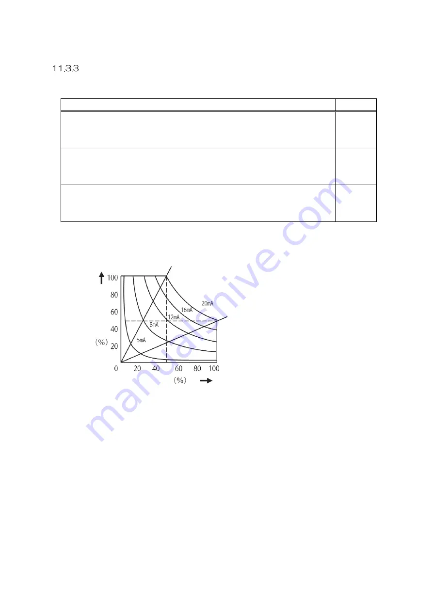
Signal current 

Load resistance curve


Output current 

Output 

voltage 

Содержание CALPOTE UG Series

Страница 1: ...ase of our Thyristor Type Power Regulator Unit CALPOTE UG1 Series In order to use this product safely and correctly read this instruction manual thoroughly before using this product Ensure that this m...

Страница 2: ...EL 30 7 1 Names and Overview of the LED Lamps and Keys 30 7 2 Operations 31 Selecting and displaying modes and items 31 Changing settings 32 7 3 Modes 33 MONITOR mode 33 PARAMETER mode 34 FUNCTION mod...

Страница 3: ...64 Checking the product 64 How to install the conversion board 65 Connection diagrams 65 11 2 Functions 66 Model list 66 Feedback control 67 Detection value adjustment function 70 Heater disconnection...

Страница 4: ...4 14 UNIT SPECIFICATIONS 85 15 OPTIONAL ITEM SPECIFICATIONS 87 APPENDIX A PARAMETER LIST 89 APPENDIX B PANEL TRANSITION DIAGRAM 94 APPENDIX C ERROR CODE LIST 95...

Страница 5: ...categories and symbols are used to explain the items that must be observed Explanation of label categories WARNING This indicates information that involves the risk of death or serious injury CAUTION...

Страница 6: ...If you detect an odd smell or sound stop work immediately and stop operating the product There is the risk of fire if this instruction is not followed Prohibited Do not use the product with the unit...

Страница 7: ...exposed to direct contact with heat from a dryer or other heat source Locations exposed to contact with water Locations where there is dust salt corrosive gas or flammable gas Outdoors 1 2 Installati...

Страница 8: ...he appropriate diameters to wire the input and output terminals There is the risk of heating or fire if the wire diameters are too small Use crimp terminals with the appropriate size to wire the input...

Страница 9: ...provide ventilation in consideration of the internal calorific value of the unit See 9 UNIT OUTLINE for the internal calorific value Note that dust moisture overheating vibration and other issues may...

Страница 10: ...when the unit is operated with a transformer load voltage higher than the rating may be generated on the load side of the unit due to surge voltage caused by gate blocking including the unit being tu...

Страница 11: ...rews nuts etc for output wiring 1 Screw For models with a rated current of 25 to 250 A 2 2 Bolt 2 3 Washer Models with a rated current of 350 or 450 A 4 4 Spring washer 2 5 Nut 2 3 Ground terminal con...

Страница 12: ...ded items refer to the installation manual that comes with each optional item Optional item Model Optional item that needs to be purchased separately Display panel UG DP Extension cable Conversion boa...

Страница 13: ...ign is safe by installing protective functions on the input side of the main circuit using breakers or other devices If the power supplied to the main circuit is not 200 220 V use a transformer to cha...

Страница 14: ...nect of temperature controller to terminal and of temperature controller to terminal Short circuit with S when the temperature controller is a current source 4 to 20 mA DC Open S when the temperature...

Страница 15: ...etermined by a combination of the three inputs Setting examples are shown in the following figure Short circuiting is not required when the settings are configured via the panel or communication HL Tw...

Страница 16: ...e panel or communication The output started via the panel or communication stops when ST is opened short circuited and then opened again Open GT Emergency stop signal This terminal is used to stop the...

Страница 17: ...utomatic 2 switching 1 to 5 VDC 8 Manual Automatic 3 switching 0 to 5 VDC 9 Control of two or more UG1 units using a single temperature controller 4 to 20 mA DC with the gradient set for each unit 10...

Страница 18: ...re controller type to 0 4 to 20 mA 1 to 5 VDC 1 Standard 2 With the gradient setting 3 With the lower point setting 4 With the gradient setting and the lower point setting Manual Manual Gradient Manua...

Страница 19: ...controller type to 2 Two position control 1 Standard 2 With the proportional setting 3 Upper limit setting only 4 Upper limit setting and proportional setting only Upper limit Lower limit Upper limit...

Страница 20: ...4 to 20 mA 1 to 5 VDC 1 Standard 2 With the gradient setting 3 With the lower point setting 4 With the gradient setting and the lower point setting Gradient Lower point Lower point Gradient Temperatu...

Страница 21: ...4 to 20 mA 1 to 5 VDC 1 Standard 2 With the gradient setting 3 With the lower point setting 4 With the gradient setting and the lower point setting Temperature controller Temperature controller Temper...

Страница 22: ...to 1 0 to 5 VDC 1 Standard 2 With the gradient setting 3 With the lower point setting 4 With the gradient setting and the lower point setting Lower point Lower point Gradient Gradient Temperature cont...

Страница 23: ...1 to 5 VDC 1 Standard 2 With the gradient setting 3 With the lower point setting 4 With the gradient setting and the lower point setting Lower point Lower point Manual Manual Manual Manual Gradient G...

Страница 24: ...1 to 5 VDC 1 Standard 2 With the gradient setting 3 With the lower point setting 4 With the gradient setting and the lower point setting Lower point Lower point Manual Manual Manual Manual Gradient Gr...

Страница 25: ...VDC 1 Standard 2 With the gradient setting 3 With the lower point setting 4 With the gradient setting and the lower point setting Lower point Lower point Manual Manual Manual Manual Gradient Gradient...

Страница 26: ...to 20 mA DC with the gradient set for each unit Set F101 Temperature controller type to 0 4 to 20 mA 1 to 5 VDC 1 When the PS terminal is not used 2 When the PS terminal is used Gradient Gradient Grad...

Страница 27: ...1 to 5 VDC with the gradient set for each unit Set F101 Temperature controller type to 0 4 to 20 mA 1 to 5 VDC 1 When the PS terminal is not used 2 When the PS terminal is used Gradient Gradient Gradi...

Страница 28: ...0 to 5 VDC with the gradient set for each unit Set F101 Temperature controller type to 1 0 to 5 VDC 1 When the PS terminal is not used 2 When the PS terminal is used Gradient Gradient Gradient Gradie...

Страница 29: ...sy locks Bundle the control power supply wires separately from other wires 6 2 Grounding As the unit is designed to be installed in the distribution panel cabinet the ground terminal at the bottom of...

Страница 30: ...when an error occurs 3 Operation status LED This LED is ON during operation It flashes while an error is occurring during operation It turns OFF when operation stops including stops due to errors 4 Mo...

Страница 31: ...key For the UG1 this key is not used 7 2 Operations This section describes basic operations common to all modes Details are explained in the section of each mode on the following pages Selecting and d...

Страница 32: ...ge the value Press or to move the digit to set The selected digit flashes Press or to increase or decrease the value The value increment decrement differs according to the item Press ESC to cancel the...

Страница 33: ...played Power 0 0 to 999 9 kW The output power is displayed 1000 to 9999 The checkable detection values differ according to the optional conversion board model The values to be displayed are also diffe...

Страница 34: ...t via the panel or communication Setting values are ignored when 0 Control terminal block is selected for F2 Priority setting Parameter list Display symbol Name Setting range Incremen t Unit Default v...

Страница 35: ...e value can be set via the panel or communication as a substitute for the temperature controller H Manual upper limit signal One of the output setting signals this signal functions in the same way as...

Страница 36: ...l value The following figure shows an example of phase control with a soft start time of 10 0 seconds Operation start stop Output setting signal Output voltage 10 0s 7 5s 2 5s 100 25 Stop Operation St...

Страница 37: ...e interval of the continuous cycle control method shown in the following figure Interval t n Function characteristics This parameter is used to select the characteristic number of the function charact...

Страница 38: ...nd change the setting by selecting the corresponding function code Function code categories Function code Category overview Function code Category overview F0 Rated value F4 Conversion board F1 Contro...

Страница 39: ...to the usage status of optional items See the following table to set the values Conversion board to use CT to use Rated current setting Rated voltage setting F408 F407 F000 F001 None Built in CT 1 3 U...

Страница 40: ...n control 0 F100 Waveform control method Select the waveform control method The following three methods are available phase control intermittent cycle control and continuous cycle control Each has the...

Страница 41: ...trol Continuous cycle control F101 Temperature controller type Select the temperature controller type Code Function name Setting range Increment Unit Default value Changeable during operation F2_P Pri...

Страница 42: ...use for each parameter 0 Control terminal block input selected The signal applied to the control terminal block is used as the setting The value entered on the setting screen in PARAMETER mode is igno...

Страница 43: ...0 100 0 of setting 0 to 100 1 The standard function characteristics can be modified to other characteristics using this function Step 1 Select the characteristic number to adjust with F300 Selection o...

Страница 44: ...Heater disconnection detection function 0 Disable standard version 1 Disable highly functional version 2 Enable standard version 3 Enable highly functional version 0 F402 Heater A count 1 to 5 1 2 0...

Страница 45: ...unction has two selectable modes the standard version and the highly functional version This function can be temporarily disabled with this parameter Select the setting that matches the desired combin...

Страница 46: ...in adjustment F405 Voltage gain adjustment F406 Power gain adjustment When accuracy is required for the feedback control the detection values can be corrected For details on the correction procedure s...

Страница 47: ...o check the model before configuring the settings Communication board model Handling of F5 function codes UG MBR The settings can be changed as necessary UG CL The settings are not required Use the co...

Страница 48: ...to when it starts responding When the unit responds too quickly a time lag can be set to allow the master to receive data Code Function name Setting range Increment Unit Default value Changeable duri...

Страница 49: ...the error detection It is used to simply switch the relay contact output destination The settings of this function do not change the output stoppage error code display and other operations taken when...

Страница 50: ...RUN STOP key lock Pressing the RUN STOP key on the display panel can be disabled This setting disables the starting and stopping of the output from the display panel Start stop switching via the ST t...

Страница 51: ...d in the history Concrete examples are shown below Errors that occur in certain situations are not added to the history For details see 8 ERROR DETECTION Set the heater resistance used in standard ver...

Страница 52: ...tops Power OFF Relay 1 Saved Er 05 Self diagnosis Thyristor open Operation stops Power OFF Relay 1 Saved Er 06 Self diagnosis Thyristor short circuit Operation stops Power OFF Relay 1 Saved Er 07 CPU...

Страница 53: ...warning relay output OFF Errors may be detected again if the power is turned back ON without first removing the error causes The unit may be damaged if it repeatedly stops due to errors Automatic reco...

Страница 54: ...d current of 100 A or higher When detected The output stops Clearing method Stop the power supply and remove the causes of the detected error Potential causes The temperature inside the distribution p...

Страница 55: ...ned When detected The output stops Clearing method Short circuit GT with PH on the control terminal block 8 7 Er 10 Power Supply Voltage Drop Detection condition The control power supply voltage has d...

Страница 56: ...ter disconnection detection function detected a heater disconnection For details see 11 2 4 Heater disconnection detection function When detected The output continues Note that the load voltage may in...

Страница 57: ...type You can forcibly clear false warnings by setting F700 Self diagnosis stop to 0 Suspend self diagnosis Self diagnosis targets differ according to the unit status Conversion board category A UG TB3...

Страница 58: ...G1 035 35 A Self cooling 3 0 57 M4 M5 M5 UG1 050 50 A Self cooling 3 0 77 M4 M5 M5 UG1 075 75 A Self cooling 3 5 113 M4 M6 M6 UG1 100 100 A Air cooling 4 0 164 M4 M6 M6 UG1 150 150 A Air cooling 5 0 2...

Страница 59: ...crew tightening torque Screw size Screw tightening torque N m M3 0 5 to 0 8 Screw on the control terminal block M4 1 5 to 1 8 M5 2 5 to 3 0 M6 6 4 to 7 4 M8 15 7 to 16 7 M10 23 5 to 26 5 M12 39 2 to 4...

Страница 60: ...60 9 2 External View Models with a rated current of 25 35 or 50 A Models with a rated current of 75 A...

Страница 61: ...61 Models with a rated current of 100 A Models with a rated current of 150 A Intake air Intake air...

Страница 62: ...62 Models with a rated current of 250 A Models with a rated current of 350 or 450 A Intake air Intake air...

Страница 63: ...the front cover and tighten the screws at the bottom of the unit 10 2 Cooling Fan Rated current of the unit Order code 100 A A00A1917200 150 A A00A1917300 250 A A00A1917400 350 A A00A1917400 450 A A00...

Страница 64: ...the functions to be used Check that all the necessary parts are present Pattern Required optional item 3 Remark A Not required B UG TB1V External PT C UG TB1A External CT main circuit CT D UG TB1A 1...

Страница 65: ...t failures Connection diagrams The wiring method differs according to the conversion board pattern The connection diagrams regarding control terminals I1 D1 and V1 are shown below The connection of ot...

Страница 66: ...l Current Voltage Power Disconnection detection No conversion board UG TB1A UG TB1V UG TB3 UG TB3H UG TB3U UG TB3HU UG TB4 UG TB4H The detection value display function shows different values according...

Страница 67: ...UG TB1A 0 No feedback 1 Constant current control UG TB1V 0 No feedback 2 Constant voltage control UG TB3 UG TB3H UG TB3U UG TB3HU 0 No feedback 1 Constant current control 2 Constant voltage control 3...

Страница 68: ...l signal Input signal Indicates parameter H manual upper limit signal or parameter P temperature control signal whichever is used Measured load value Indicates the measured value of the load current l...

Страница 69: ...2 Constant power control E G I Maximum load voltage Maximum load current and Rated voltage of the external PT Rated current of the main circuit CT 1 Maximum load voltage Maximum load current or Rated...

Страница 70: ...tion value adjustment function The accuracy may decrease from the specifications according to the combination of the unit optional items and load When the conversion board is installed or replaced be...

Страница 71: ...urrent on the heater A side Detection method Monitor the heater resistance via the external CT and external PT Disconnection is determined with an amount of change from the initial resistance Monitor...

Страница 72: ...d voltage are obtained via the main circuit CT external CT external PT and conversion board 2 The load current and load voltage in the early phase of operation are memorized 3 The resistance when the...

Страница 73: ...xt section is also available with this function Note that the function does not work correctly if the highly functional version is selected by mistake Parameter U Heater disconnection amount Set the t...

Страница 74: ...ection highly functional version 1 Divide the number of heaters by two so that A is equal to B or B 1 2 The number of heaters connected to the A side and the B side are memorized by the unit 3 The loa...

Страница 75: ...ction detection function Select 3 Enable highly functional version to enable the highly functional version function When the function needs to be temporarily disabled for test operation or other purpo...

Страница 76: ...f detection is performed normally Step 1 Perform operation for at least 5 minutes with the number of parallel connected heaters used to set parameter U Step 2 Check that error code Er 13 is not displa...

Страница 77: ...S Power supply voltage Load fluctuation Ambient temperature Constant 10 times the rated load Constant 2 FS Power supply voltage Load Ambient temperature fluctuation Constant Constant 10 C to 50 C 2 FS...

Страница 78: ...mperature Rated voltage 10 Constant Constant 1 FS Power supply voltage Load fluctuation Ambient temperature Constant 10 times the rated load Constant 1 FS Power supply voltage Load Ambient temperature...

Страница 79: ...tant 1 FS Power supply voltage Load fluctuation Ambient temperature Constant 4 times the rated load Constant 5 FS Power supply voltage Load Ambient temperature fluctuation Constant Constant 10 C to 50...

Страница 80: ...oltage fluctuation Load Ambient temperature Rated voltage 10 Constant Constant 1 FS Power supply voltage Load fluctuation Ambient temperature Constant 10 times the rated load Constant 1 FS Power suppl...

Страница 81: ...View Wiring terminals Primary side M4 Secondary side M3 Wiring terminal processing None Process them according to your usage conditions External CT optional item External PT optional item For 210 V an...

Страница 82: ...unication When the warning circuit is activated an error code is displayed on the display panel on the front surface of the product Check the error code Resume operation after removing causes accordin...

Страница 83: ...Check the setting Is the AT terminal setting correct Check the setting Does the phase of the main circuit power supply match that of the control power supply Match the phases Abnormal output If consta...

Страница 84: ...ed Are the detection lines open Check the wiring If constant power control is used are the external CT main circuit CT and external PT polarities correct Check the polarities A THY error has occurred...

Страница 85: ...the control power supply units with 100 A or higher Control method Phase control intermittent cycle control continuous cycle control Feedback control is not available with the continuous cycle control...

Страница 86: ...or the continuous cycle control method linearity 5 FS Characteristics of roots of 1 6 1 8 2 0 2 2 2 5 and 3 0 power and average characteristics are available with the function characteristic function...

Страница 87: ...s Power supply voltage fluctuation Rated voltage 10 1 FS Load 10 times the rated load 1 FS Ambient temperature 10 C to 50 C 2 FS Constant power control characteristics when the built in CT is used Pow...

Страница 88: ...th variable resistance Disconnection detectable range Output current that is 30 of the rating or higher Maximum number of parallel connected loads 10 External PT For 110 V Rated primary input 110 V 10...

Страница 89: ...l upper limit signal 0 0 to100 0 0 1 0 0 L Lower point lower limit signal 0 0 to100 0 0 1 0 0 F Gradient proportional signal 0 0 to100 0 0 1 100 0 E Soft start time 0 0 to300 0 0 1 s 0 5 C Current lim...

Страница 90: ...l P 0 Control terminal block input 0 F2_H Priority of the upper limit signal H 1 Panel 0 F2_L Priority of the lower point signal L 2 Communication 0 F2_F Priority of the gradient signal F 0 F2_E Prior...

Страница 91: ...aracteristic 5 Characteristic 6 Characteristic 7 0 0 of setting 0 0 0 0 0 0 0 10 0 of setting 24 28 32 35 40 46 9 20 0 of setting 37 41 45 48 53 58 22 30 0 of setting 47 51 55 58 62 67 37 40 0 of sett...

Страница 92: ...t gain adjustment 1 to 9999 1 A 0 F405 Voltage gain adjustment 1 to 999 9 0 1 V 0 F406 Power gain adjustment 1 to 999 9 0 1 kW 0 F407 CT selection 0 External CT 1 Built in CT 0 F408 Conversion board m...

Страница 93: ...607 Er 07 CPU error 3 Output to both 0 F608 Er 08 Memory error 0 F609 Er 09 Emergency stop 0 F610 Er 10 Power supply voltage drop 2 F611 Er 11 Instantaneous voltage drop 2 F612 Er 12 Frequency error 2...

Страница 94: ...94 APPENDIX B PANEL TRANSITION DIAGRAM...

Страница 95: ...Saved Er 07 CPU error Operation stops Power OFF None Not saved Er 08 Memory error Operation stops Power OFF None Not saved Er 09 Emergency stop Operation stops Automatic recovery None Saved only duri...

Страница 96: ...MEMO...

Страница 97: ...CORPORATION 50 Seaview Boulevard Port Washington NY 11050 4618 U S A TEL 1 516 625 1313 FAX 1 516 625 8845 https www sanrex com https sanrexwelding com SANREX ASIA PACIFIC PTE LTD Block 5000 Ang Mo Ki...

Отзывы: