background image

KBox B-201 -  User Guide, Rev. 1.3 


www.kontron.com 


// 54 


11/


External Interface - Pin Assignments 

11.1.


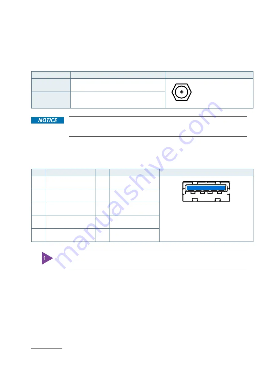
DC IN Power Connector Pin Assignment 

The DC IN power connector is a barrel jack (5.5 mm/ 2.5 mm) with center pole and an input voltage of 12 V only. 

Table 16: DC power Jack Pin Assignment 

Pin 

Signal Name 

Power Jack 

Centre pole 

12 V 


Outer ring 

Ground 


Hot plugging the power connectors might damage the board and is not allowed. 
When connecting to the mainboard, turn off the mains supply to make sure all power lines 
are turned off. 


11.2.


USB 3.0 Connector Pin Assignment 

Table 17: USB 3.0 Connector Pin Assignment 

Pin 

Signal Name 

Pin 

Signal Name 

9-pin USB 3 (Type A) Port 

+5V (fused protected) 
 

RX- 

9                                       5 


1                              4 


Date- 
 

RX+ 

Data+ 
 

GND 

GND 
 

TX- 


TX+ 


Low-active signals are indicated by a minus sign.


Содержание Kontron KBox B-201

Страница 1: ...USER GUIDE www kontron com 1 KBox B 201 Doc User Guide Rev 1 3 Doc ID 1062 7377...

Страница 2: ...KBox B 201 User Guide Rev 1 3 www kontron com 2 This page has been intentionally left blank...

Страница 3: ...be suitable for the specified use without further testing or modification Kontron expressly informs the user that this user guide only contains a general description of processes and instructions whi...

Страница 4: ...or resale THIS PRODUCT IS NOT DESIGNED MANUFACTURED OR INTENDED FOR USE OR RESALE FOR THE OPERATION OF APPLICATION IN A HAZARDOUS ENVIRONMENT OR REQUIRING FAIL SAFE PERFORMANCE OR IN WHICH THE FAILUR...

Страница 5: ...es contact information on the last page of this user guide or visit our website CONTACT US Customer Support Find Kontron contacts by visiting http www kontron com support Customer Service As a trusted...

Страница 6: ...cribed by the law may endanger your life health and or result in damage to your material ESD Sensitive Device This symbol and title inform that the electronic boards and their components are sensitive...

Страница 7: ...ound cable shall be the last cable to be disconnected or the first cable to be connected when performing installation or removal procedures on this product Special Handling and Unpacking Instruction E...

Страница 8: ...re pack it in the same manner as it was delivered Special care is necessary when handling or unpacking the product See Special Handling and Unpacking Instruction Quality and Environmental Management...

Страница 9: ...Connectors 20 4 3 Left and Right Side Views 22 4 4 Top Cover and Bottom Views 23 5 System Extension 24 5 1 External Storage 24 5 1 1 2 5 SSD Drive Bay 24 5 2 Internal Expansion 24 5 2 1 mSATA mPCIe S...

Страница 10: ...d 53 11 External Interface Pin Assignments 54 11 1 DC IN Power Connector Pin Assignment 54 11 2 USB 3 0 Connector Pin Assignment 54 11 3 USB 2 0 Connector Pin Assignment 55 11 4 LAN GbE Connector Pin...

Страница 11: ...Assignment 57 Table 24 PS 2 Mouse Connector Pin Assignment 57 Table 25 Audio Line out Audio Line in Pin Assignment 57 Table 26 Serial Interface COM1 port RS232 Connector Pin Assignment 58 Table 27 Na...

Страница 12: ...nting Position 41 Figure 31 Non VESA Stand Monitor Assembly 42 Figure 32 Installed VESA 100 Mount Assembly on a non VESA Stand Monitor 42 Figure 33 VESA Monitor Stand Assembly 43 Figure 34 Installed V...

Страница 13: ...circulation is available to cool the product please ensure that the ventilation openings are not covered or blocked If an air filter is provided this should be cleaned regularly Do not place the prod...

Страница 14: ...herefore may not be connected to such devices 1 1 Electrostatic Discharge ESD A sudden discharge of electrostatic electricity can destroy static sensitive devices or micro circuitry Proper packaging a...

Страница 15: ...eplacing Lithium Battery Danger of explosion when replacing with wrong type of battery Replace only with the same or equivalent type recommended by the manufacturer The lithium battery type must be UL...

Страница 16: ...n multiple user applications such as behind a monitor wall mount horizontal and vertical or as a desktop version horizontal and vertical Additionally the KBox B 201 s extensive onboard interfaces and...

Страница 17: ...ies Part Part Description Vertical Stand Metal stand to position the KBox B 201 vertically on a desktop Mounting Brackets Two mounting brackets that attach to the KBox B 201 s sides for wall mounting...

Страница 18: ...rformance needs with 6th Gen or 7th Gen Intel Core platforms with a mini ITX mainboard and extensive interfaces on the rear panel A M 2 Key B socket and a shared mSATA mPCIe full size half size socket...

Страница 19: ...des an integrated power LED that lights up blue to indicate the powered on state By pressing the power on button for longer than four seconds a forced system shutdown will be initiated before the powe...

Страница 20: ...d connector For the pin assignment refer to Chapter 11 7 PS 2 Keyboard Connector Pin Assignment 4 2 1 2 PS 2 Mouse The standard 6 pin mini DIN PS 2 connector enables the connection of a mouse The PS 2...

Страница 21: ...gabit Ethernet 10 100 1000 Mbit s IEEE 1588 capable with a standard 8 pin RJ45 connector including two status LEDs for speed 10 100 1000 Mbit s link and activity For the pin assignment refer to Chapte...

Страница 22: ...o threaded screw holes available on both sides Figure 6 pos 2 are used to attach mounting brackets see Chapter 8 3 Mounting Brackets Option or alternatively to attach the vertical stand see Chapter 8...

Страница 23: ...n metal plate underneath The bottom side contains an external 2 5 SSD drive bay that opens or closes using a single screw Figure 8 pos 3 The four threaded holes Figure 8 pos 2 enable the KBox B 201 to...

Страница 24: ...cards When considering whether to install a full size half size mSATA or mPCIe expansion card users must take into consideration whether a M 2 2242 or M 2 2260 form factor card is installed in the ne...

Страница 25: ...attention to the power specification and ensure that the overall power consumption does not exceed the PSU power specification of 150 W Please follow the safety instructions for components that are s...

Страница 26: ...t slide the top cover off the chassis To avoid contact between the top cover and the internal fan assembly once the top cover is free from the holding brackets on the front panel lift the top cover ve...

Страница 27: ...move the screw that secures the SSD drive bay cover Figure 8 pos 3 4 Lift the SSD drive bay cover a few centimeters to release the SSD from SSD holding plate on the rear side of the SSD drive bay cove...

Страница 28: ...Closing SSD Drive Bay Cover step 7 After installing or removing a 2 5 SSD the partitioning of the memory maybe different To remove a 2 5 SSD perform the following 1 Open the SSD drive bay cover by fo...

Страница 29: ...down the product properly and disconnect the connection to the power source Disconnect all peripherals 2 Open the Chassis as described in the Chapter 6 1 Opening and Closing the Chassis steps 1 to 5 3...

Страница 30: ...Gently pull the mSATA card out of the mSATA socket 6 Close the Chassis as described in the Chapter 6 1 Opening and Closing the Chassis steps 1 to 4 After installing or removing an mSATA SSD the parti...

Страница 31: ...ll peripherals 2 Open the chassis as described in the Chapter 6 1 Opening and Closing the Chassis steps 1 to 5 3 Locate the mPCIe card installed into your product 4 Remove the mountings screw and spac...

Страница 32: ...e 15 pos 1 2 3 Obstructing the ventilation holes may cause overheating Do not to place items directly in front of the top cover ventilation holes and observed that all ventilation openings are not cov...

Страница 33: ...the correct mount orientation Leave sufficient clearance keep out area to prevent the product from overheating To ensure proper operation use the specified recommended keep out areas of Top cover 10...

Страница 34: ...he local national regulations for grounding The voltage feeds must not be overloaded Adjust the cabling and the overcurrent protection to correspond with the electrical figures indicated on the type l...

Страница 35: ...ve stability positioning the chassis feet between the mounting hole and the outside edge 8 1 1 Mount Option The KBox B 201 with chassis feet can be operated in the upwards horizontal position only as...

Страница 36: ...is to be fastened facing upwards 2 Aline the two vertical stand screw holes with the two threaded screw holes on the chassis s side 3 Using a torx 08 x60 screwdriver fasten the vertical stand to the...

Страница 37: ...e mounting surface as the bottom side does not contain ventilation holes and the mounting holes shown in Figure 21 pos 2 can be used Obstructing the ventilation holes may cause overheating Do not to p...

Страница 38: ...while observing the specified clearance of 10 mm keep out area shown in Figure 22 and Figure 23 Figure 22 Keep Out Areas with Top Cover facing the Mount Surface Figure 23 Keep Out Areas with Bottom S...

Страница 39: ...ng Do not mount with the top cover facing downward inverted orientation Use the allowed mount orientations only Horizontally top cover facing upwards Vertically top cover facing the mount surface Vert...

Страница 40: ...lowing 1 View the KBox B 201 s bottom side to check that no chassis feet are installed If feet are installed removed the feet before mounting the KBox B 201 on the VESA 100 mounting frame 2 Align the...

Страница 41: ...ing frame as shown in Figure 29 Positioning the PSU 6 Slot the PSU with the 3 pin AC connector facing towards the bottom of the VESA 100 mounting frame into the gap made in step 5 and feed the PSU bet...

Страница 42: ...t assembly only vertical mounting is possible 8 4 1 1 Mounting on non VESA Mount Stand Monitor 1 Feed the four supplied M4x 20 mm screws through the four mount hole on the VESA mount frame and attach...

Страница 43: ...attach one of the supplied spacers to the screw s free end Figure 33 Figure 33 VESA Monitor Stand Assembly 3 First insert the free end of the screw with spacer through the four mount hole on the VESA...

Страница 44: ...he DC IN connector on the rear panel see Figure 5 pos 10 5 Connect the other end of the PSU to a mains power source 6 Press the front panel Power on button see Figure 4 pos 3 7 The KBox B 201 is now i...

Страница 45: ...fully operational when powered on for the first time If ordered without a pre installed OS users need to install the OS and the appropriate drivers in accordance with the ordered hardware configurati...

Страница 46: ...d Chipset Onboard connectors External interfaces CPU Onboard controller Onboard memory Dual Channel DDR4 2400 up to 32 GB CPU 7th Den Lntel ore i3 i5 i7 Power on Button Power LED 4x USB 3 0 4x USB 2 0...

Страница 47: ...Table 4 Processor Specification Type Intel i3 7101E Intel i5 7500 Intel i7 7700 Core 2 4 4 Cache 3 MB 6 MB 8 MB Smart Processor Base Frequency 3 9 GHz 3 4 GHz 3 6 GHz TDP 54 W 65 W 65 W Graphics Inte...

Страница 48: ...e SATA III Configured via BIOS setup M 2 1x M 2 2242 2260 22 pin length 42 mm length 60 mm It is possible to install the following expansion cards combinations together mSATA mPCIe full size M 2 2242...

Страница 49: ...nting Options Mounting bracket depth x width x height 187 mm x 45 mm x 20 mm 7 36 x 1 77 x 0 79 Vertical stand depth x width x height 187 mm x 100 mm x 12 mm 7 36 x 3 94 x 0 47 VESA 100 mount assembly...

Страница 50: ...KBox B 201 User Guide Rev 1 3 www kontron com 50 Figure 38 Dimensions Top Cover Figure 39 Dimensions Bottom Side 190 mm 190 mm 190 mm 190 mm 6 5 mm...

Страница 51: ...Environmental Specification Temperature Operating 0 C 45 C 32 F 113 F Storage Transit 20 C 80 C 4 F 176 F Relative Humidity Operating 93 RH 40 C non condensing Storage Transit Altitude Operating 5000...

Страница 52: ...ations Commission FCC 47 CFR part 15 ICES 003 rules to limit the potential of harmful interference The FCC class is dependent on the implemented PSU Environment WEEE Directive Directive 2002 96 EC Com...

Страница 53: ...e D x W x H 171 mm x 72 mm x 40 mm Input Voltage Range 100 VAC 240 VAC Input Current 2 A Max Efficiency 86 min 100 VAC 12 5 A Load Output Voltage 12 V DC Output Current 12 5 A max 150 W 10 6 2 Power C...

Страница 54: ...me Power Jack Centre pole 12 V Outer ring Ground Hot plugging the power connectors might damage the board and is not allowed When connecting to the mainboard turn off the mains supply to make sure all...

Страница 55: ...indicated by a minus sign 11 4 LAN GbE Connector Pin Assignment Table 19 LAN GbE Connector Pin Assignment Low active signals are indicated by a minus sign Table 20 LAN Link Activity Speed Mbps LINK AC...

Страница 56: ...tect 18 19 GND return 3 3V fuse protested 20 Low active signals are indicated by a minus sign 11 6 DVI D Connector Pin Assignment Table 22 DVI D Connector Pin Assignment Pin Signal Name Pin Signal Nam...

Страница 57: ...female barrel connector supports audio line out green and audio line in blue high definition audio signals or legacy audio signals selectable in the BIOS setup menus Table 25 Audio Line out Audio Line...

Страница 58: ...able 26 Serial Interface COM1 port RS232 Connector Pin Assignment Pin Signal Name RS232 9 pin D SUB Connector 1 DCD Data Carrier Detect 1 5 6 9 2 SIN Signal In 3 SOUT Signal out 4 DTR Data Terminal Re...

Страница 59: ...t the uEFI BIOS Setup program perform the following 1 Power up the board 2 Wait until the first characters appear on the screen POST messages or splash screen 3 Press the DEL key 4 If the uEFI BIOS is...

Страница 60: ...te To ensure compatibility with new operating systems OS hardware or software and to integrate new BIOS functions Kontron recommends updating the BIOS For information regarding KBox B 201 mainboard BI...

Страница 61: ...or replaced within the stipulated warranty period Follow these steps before returning any product to Kontron 1 Visit the RMA Information website http www kontron com support and services support rma...

Страница 62: ...nt from Kontron Europe requires only minimum servicing and maintenance for problem free operation Cleaning For light soiling clean the product with a dry cloth Carefully remove dust from the surface o...

Страница 63: ...onor the warranty even during the warranty period and shall be exempted from the statutory accident liability obligations in the event of damage caused to the product due to failure to observe the fol...

Страница 64: ...mPCIe Mini PCI Express OS Operating System PCH Platform Controller Hub PS Power Supply PSU Power supply Unit RAM Random Access memory REACH Registration Evaluation Authorization and restriction of Ch...

Страница 65: ...cts and tailor made solutions based on highly reliable state of the art embedded technologies Kontron provides secure and innovative applications for a variety of industries As a result customers bene...

Отзывы: