70
Chapter 5 VARIOUS FUNCTION ICONS
5.12.1 PULSE LENGTH
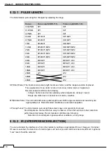
The transmission pulse length is changed by adjusting the range.
Range
Pulse Length(SMR-715)
Pulse Length(SMR-720)
0.0625NM
SP1
SP1
0.125NM
SP1
SP1
0.25NM
SP1
SP1
0.5NM
SP1/MP1
SP1/MP1
0.75NM
SP2/MP1
SP2/MP1
1NM
SP2/MP1
SP2/MP1
1.5NM
SP2/MP1/MP2
SP2/MP1/MP2
2NM
SP3/MP1/MP2
SP3/MP1/MP2
3NM
SP3/MP1/MP2
SP3/MP1/MP2
4NM
SP3/MP1/MP2
SP3/MP1/MP2
6NM
MP2/LP1
MP2/LP1/LP2
8NM
MP2/LP1
MP2/LP1/LP2
12NM
MP2/LP1
MP2/LP1/LP2
16NM
MP2/LP1
MP2/LP1/LP2
24NM
LP1
LP2
32NM
LP2
48NM
LP2
SP(Short Pulse): The transmission pulse length becomes shorter, and the range resolution improved.
The suppression of sea clutter return or rain/snow clutter return is heightened.
Recommended conditions are following.
・
In bays / harbors and narrow waterway where targets are densely crowed.
・
Rough sea state due to torrential rain or stormy weather.
MP(Middle Pulse): The normal transmission pulse length is set. Both range resolution and sensitivity are
appropriately set. Recommended conditions are General navigation.
LP(Long Pulse): The transmission pulse length becomes longer, and sensitivity improved.
Small targets are zoomed and are easy to observe. When the sea state is bad, detection
performance decreases. Recommended conditions are following.
・
Detection of small targets in good weather conditions, at long range.
5.12.2 IR (INTERFERENCE REJECTION)
You can eliminate the interference from other radars by setting an appropriate IR level. However, if a higher
IR level is selected, the detection of small targets such as buoys and small boats become difficult. In general
“Low” level should be selected.
Содержание SMR-715 series
Страница 1: ...MARINE RADAR EQUIPMENT INSTRUCTION MANUAL...
Страница 2: ......
Страница 15: ...xiii EQUIPMENT APPEARANCE NKE 1066 SCANNER UNIT NKE 2044 SCANNER UNIT...
Страница 29: ...Chapter 1 INSTALLATION 3 1 2 3 DIMENSIONAL DRAWING OF DISPLAY MOUNTING...
Страница 30: ...Chapter 1 INSTALLATION 4...
Страница 31: ...Chapter 1 INSTALLATION 5 1 2 4 EXAMPLES OF DISPLAY MOUNTING DESK TOP INSTALLATION Mounting bracket...
Страница 32: ...Chapter 1 INSTALLATION 6 DESKTOP MOUNTING TEMPLATE Note Please note the paper size 182 257...
Страница 34: ...Chapter 1 INSTALLATION 8 FLUSH MOUNTING TEMPLATE Note Please note the paper size 182 257...
Страница 43: ...Chapter 1 INSTALLATION 17 NKE 2044 2FT SCANNER Fig 1 3 6 3 Fig 1 3 6 4...
Страница 47: ...Chapter 1 INSTALLATION 21 Fig 1 4 1 3...
Страница 51: ...Chapter 1 INSTALLATION 25 Fig 1 4 2 3...
Страница 157: ...131 Chapter 10 AFTER SALE SERVICE 10 4 RADAR FAILURE CHECK LIST SMR...
Страница 159: ...133 Chapter 12 SPECIFICATIONS Chapter 12 SPECIFICATIONS...
Страница 160: ...134 Chapter 12 SPECIFICATIONS 12 1 SCANNER DIMENSION 12 1 1 NKE 1066 4 40 RUBBER PLATE...
Страница 161: ...135 Chapter 12 SPECIFICATIONS 12 1 2 NKE 2044...
Страница 162: ...136 Chapter 12 SPECIFICATIONS 12 2 DISPLAY DIMENSION 12 2 1 SMR 715 720...
Страница 163: ...137 Chapter 12 SPECIFICATIONS...
Страница 172: ...APPENDIX A 1 APPENDIX NKE 1066 1 5FT SCANNER INTERCONNECTION DIAGRAM FIG A1...
Страница 173: ...APPENDIX A 2 NKE 2044 2FT SCANNER INTERCONNECTION DIAGRAM FIG A2...
Страница 174: ...APPENDIX A 3 SMR 715 720 DISPLAY UNIT INTER CONNECTION DIAGRAM FIG A3...
Страница 175: ...APPENDIX A 4 SMR 715 720 PRIMARY POWER SUPPLY DIAGRAM FIG A4...
Страница 176: ...APPENDIX A 5 SMR 715 720 INTERCONNECTION DIAGRAM FIG A5...
Страница 177: ...APPENDIX A 6 MEMO...
Страница 187: ...APPENDIX A 16 DECLARATION OF CONFORMITY...
Страница 188: ...APPENDIX A 17...
Страница 189: ...APPENDIX...
Страница 191: ...Chapter 3 ADJUST THE RADAR ECHO A 2...
Страница 192: ...Chapter 3 ADJUST THE RADAR ECHO...

