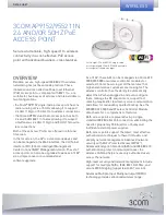
WEA412h (Indoor type) Quick Installation Manual
Introduction
What is WEA412h?
WEA412h is an Access Point (AP) which supports IEEE 802.11ac wave1 standards and
it connects wireless devices such as smartphone, laptop, tablet and etc. to a wired
network in a hospitality environment such as hotel, dormitory, and condominium.
The WEA412h supports the following features.
- IEEE 802.11a/b/g/n/ac standards
- 2.4 GHz and 5 GHz concurrent radios.
- 2 × 2 Multiple Input Multiple Output (MIMO)
- Gigabit Ethernet 1 port (PoE In) for a WAN connection
- Gigabit Ethernet 4 ports (PoE Out 1 port) for an uplink connection for wired network
- Power over Ethernet (PoE) IEEE 802.3af/802.3at
- External 48 V/0.75 A power adaptor (Optional).
- PoE Output of 10 watts max with 802.3at mode or using 48 V/0.75 A power adaptor.
- A tricolored LED displaying the operational status of WEA412h.
- One USB port (Host 2.0)
Components
After unpacking the WEA412h, confirm that all of the following items have been included:
WEA412h
Bracket for the standard junction box
(standard gang junction box)
Four Phillips screws
(UNC #6-32, L8)
Two Security Torx
(T10) screws
Installation
Manual
Ordered separately
Wall Mount Bracket
Four plastic anchors
Four Phillips screws (M4, L50)
- It is recommended to keep all packaging materials and the box.
- The power adaptor is sold separately. If necessary, contact the retailer.
Names and Functions
Front and Rear View
Ethernet Port (PoE In)
Bottom View
Ethernet Port
(PoE Out)
Ethernet
Port
LED status
indicator
Side View
Torx Security Screw Hole
Kensington Security Slot
USB
Factory Reset Switch
Right Side
Torx Security Screw Hole
DC Input
Left Side
Interface
Port Name
Description
Tricolored LED
Displays the operational status of WEA412h using a tricolored LED.
DC Input
This is for connecting the power adapter.
Ethernet Port (PoE In) Supports 1000 BASE-T Gigabit Ethernet and IEEE 802.3af/802.3at PoE mode.
Ethernet Port
(LAN1~LAN4)
Supports 1000 BASE-T Gigabit Ethernet and a PoE Output for the LAN1 port.
USB Port
Supports BLE and ZigBee dongle and provides the 2.5 W output power.
Factory reset switch
Used to reset the WEA412h to the initial factory settings.
LED status indicator
LED
Status
Description
System start status
White On
Initial LED status
Blue On
Device reset and test in progress
Red On
Booting failure (Device reset failure)
Provisioning status
Red, Green, and
Off repeatedly
APC connection in progress (Network link normal)
Green blinking
CAPWAP connection in progress (APC server connection normal)
Normal operation
status
Green On
When there is no connected wireless device
Blue On
When there is a connected wireless device
Upgrade
Blue blinking
Software upgrade in progress
Error status
Red blinking
Physical connection error of network
Yellow blinking
IP address conflict
Purple blinking
Dynamic IP address allocation failure
Bluish-green blinking Logical connection error of network
Off
Wireless interface error
Installation
WEA412h can be installed on a general wall or on the standard junction box.
Please confirm that all of the components have been included before installation.
Before Installation
Safety Requirements
Carefully observe the following safety warnings in order to avoid the risk of damage or injury.
For safe use, make sure to be well-informed.
- There is a risk of electrical shock. Make sure that the power is turned off during installation. Do not proceed
with the installation if there is any electrical current leaking. It may cause a serious electric shock.
- Wear anti-static gloves or take an appropriate action to prevent ESD when handling the product.
- Do not connect a phone line to an Ethernet port. This may damage the product.
- This product must be connected to a power supply in compliance with IEEE 802.3af/at or connected to a
limited power supply in compliance with IEC60950.
- This product must be installed in a vertical direction. To prevent damage of a product and burns of a user
due to heat caused when the product is installed in a horizontal direction, an operation of wireless LAN is
compulsorily restricted when the surface temperature of the product exceeds IEC60950 standards (95°C).
- This product must be installed or removed by only appropriately trained service personnel.
- This product operates in the Safety Extra Low Voltage (SELV) state in compliance with IEC60950.
- All the connected equipment including this product must be installed inside of the same building.
For more details, refer to the Environment A of IEEE 802.3af/at standards.
- During installation, this product must be installed at least 3 m or more apart from WiBro/3G/4G repeater or
antenna.
Installation Instructions
The following instructions must be carefully observed during installation.
- The system must be installed in a place that is easily accessible for product installation,
cable connections, and maintenance.
- The PoE cable must be always installed away from any electrical interference source
such as power lines, fluorescent lights or transmitters.
- The PoE cable must be Cat 5e or higher.
- When PoE is unavailable, a power adapter (sold separately) can be used.
The 3-pin (including ground) power socket that supplies 100~240 V AC, 50~60 Hz must
be located within 2 m from each equipment and the power must be supplied through an
independent circuit breaker.
It is recommended to use the equipment that uses a filter or a surge.
- Whether a USB port and a PoE output port (LAN1/PoE Out) operate or not according to
a power pull-in source is as follows.
1) Power adapter: an USB port (2.5 W) and a PoE output port (15.4 W) available
2) 802.3at: an USB port (2.5 W) and a PoE output port (10 W) available
3) 802.3af: both an USB port and a PoE output port are disabled
This manual describes the Wireless Enterprise WEA412h configuration and
installation instructions.


