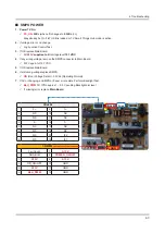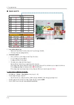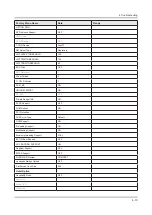
BACKLIGHTS
CNL802
CNM803
CN202
CNM803
1
Fail Count
7
A13V
2
ANA-DIM
8
POWER_ON/OFF
3
A13V
9
A13V
4
OD_ON/OFF
10
GND
5
A13V
11
GND
6
BLU_PWM
12
GND
CNL802
1
2+
9
1+
2
NC
10
NC
3
NC
11
NC
4
2-
12
1-
5
NC
13
NC
6
NC
14
NC
7
NC
15
IF2
8
NC
16
IF1
Activate Backlights Test
1.
:
Disconnect Lead Cable from Main Board to Power Supply. (CN202)
-
TV Screen for active backlight LEDs.
√
If NO BACKLIGHTS
2.
Plus (+) & Minus (-) pin voltages on the Panel Connector.
√
If no pin voltages replace SMPS.
-
If voltages exist but no backlight:
-
The highest pin voltage (BL Drive Supply )
√
Remove Panel connector and measure again to compare.
-
If the voltage was high and stays the same high reading a string of Panel LEDs are open. Replace the Panel.
-
If the v
-
oltage was low
and remains low the
SMPS
is defective.
If the voltage was low and goes high a string of panel LEDs are shorted replace the
-
Panel
.
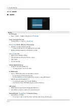
For BACKLIGHT DIMMING PROBLEMS:
Go to
•
Menu
→
Picture
→
Backlight
and vary level (0 – 20)
If no backlight changes observed:
•
Panel Connector pin voltages and BLU_PWM voltages (CNM803) while changing backlight level.
√
If Panel voltages don’t change, and BLU_PWM changes, replace
•
SMPS
.
If BLU_PWM doesn’t change replace
•
Main/T-Con Board
.
4-4
4. Troubleshooting
Содержание UN KU650DF Series
Страница 63: ...2 14 2 Product specifications 2 3 NEW Key Features 2 3 1 16 New UI Smart Hub APPS Service ...
Страница 65: ...2 16 2 Product specifications 2 4 1 123 Key 2 4 2 EXTRA Key ...
Страница 76: ...PANEL If Noisy 1 Panel defective 4 7 4 Troubleshooting ...
Страница 111: ...5 2 5 Wiring Diagram 5 1 2 55 inch Speaker L Speaker R SMPS Main board Function IR Module BT WIFI Module ...
Страница 112: ...5 3 5 Wiring Diagram 5 1 3 65 inch Speaker L Speaker R SMPS Main board Function IR Module BT WIFI Module ...


