2
.6
C
HAPTER
T
WO
: I
NSTALLATION
I
N S TA L L AT I O N
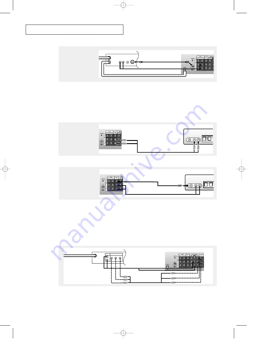
VCR Rear Panel
IN
OUT
ANTENNA
VIDEO
OUT
AUDIO
OUT
L
R
TV Rear Panel
S-Video Cable
S-VIDEO
OUT
3
Connect an S-video
cable between the
S-VIDEO OUT jack on
the VCR and the
S-VIDEO INPUT
jack on the TV.
Connecting a Second VCR to Record from the TV
Your TV can send out signals of its picture and sound to be recorded by a second VCR.
To do this, connect your second VCR as follows:
VCR Input Panel
Audio Cable
AUDIO
IN
VIDEO
IN
L
R
TV Rear Panel
1
Connect a set of audio
cables between the
AUDIO OUT jacks on the
TV and the AUDIO IN
jacks on the VCR.
An S-video cable is usually included with an S-VHS VCR. (If not, check your local
electronics store.)
TV Rear Panel
VCR Input Panel
AUDIO
IN
VIDEO
IN
L
R
Video Cable
2
Connect a video cable
between the VIDEO OUT
jack on the TV and the
VIDEO IN jack on the
VCR.
Refer to your VCR’s instructions for more information about how to record using this kind
of connection.
(The VCR input jacks might be either on the front or on back of the VCR.)
Connecting a Digital TV Set-Top Box
(For models HCJ552W/HCJ652W)
Connect the Y, Pb, and Pr video outputs of the set-top box to their corresponding inputs on
the TV. Next, connect the Left and Right audio from the set-top box to the corresponding L
and R terminals on the TV. (The connections for a typical set-top box are shown below.)
TV Rear Panel
Set Top Box Rear Panel
ANTENNA IN
VIDEO OUT
AUDIO OUT
Y
L
Pr
Pb
R
Audio Cable
Video Cable
When switching to the DTV mode, either 480p or 1080i format is automatically selected
according to the input signal.
Note: Only 480p and 1080i formats are supported in their original formats.
00578C(E)-CHAPTER 2 7/3/00 4:39 PM Page 6


