background image


English     5


Setting up Your LCD TV/Monitor


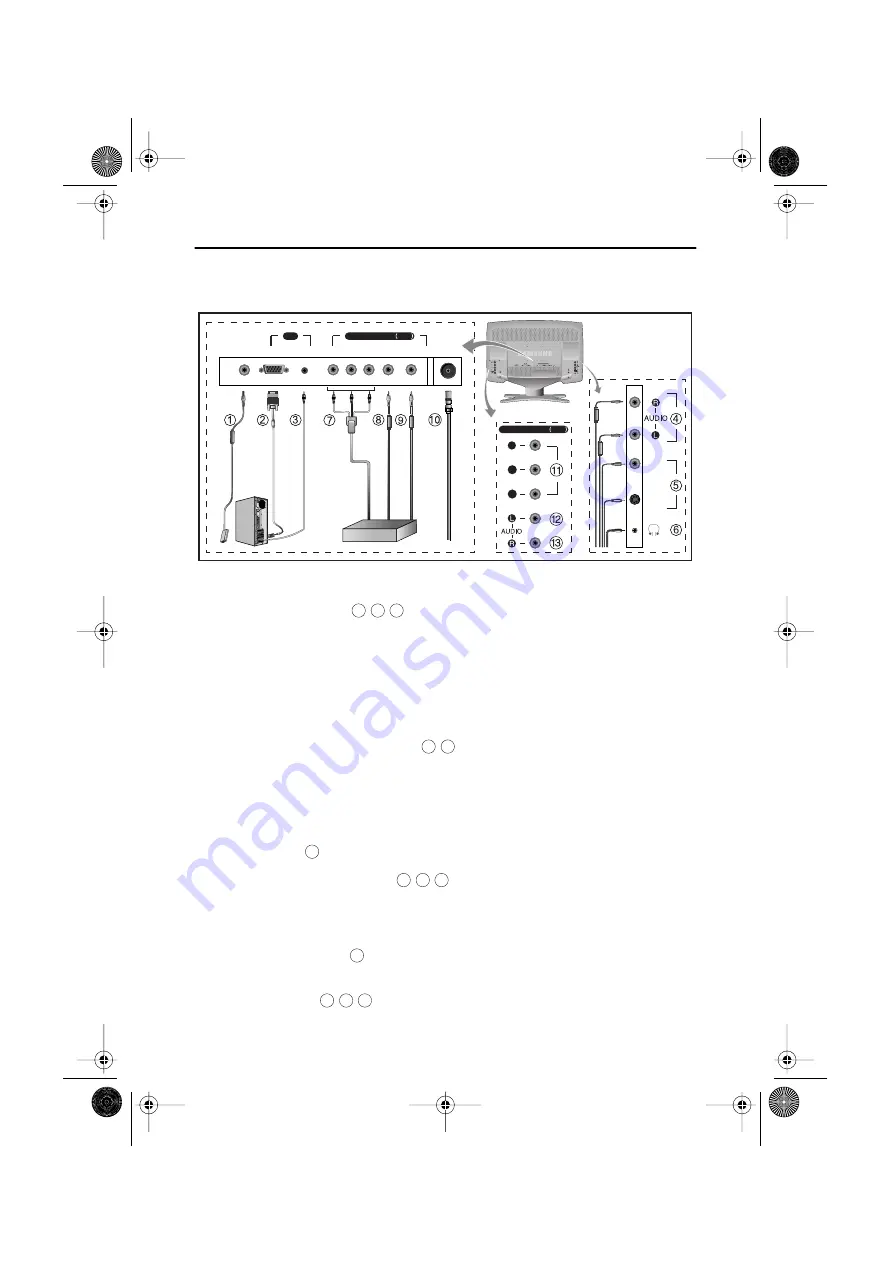
Connecting Your LCD TV/Monitor


Figure 2. Cable connections


1. Connecting 

Computer (  )


A. Connect the power cord to the DC Adaptor and connect the adaptor jack to the DC 14V

power connector on the back of the TV/Monitor.

B. Connect the 15-pin D-SUB of the video signal cable to the PC video connector on the

back of the TV/Monitor.

C. Connect the stereo audio cable to “Audio (ST)” on the  back of the TV/Monitor and the

other end to “ Audio Out” terminal of the sound card on your computer.

D. If 

necessary, install 

TV/Monitor driver contained on the 

supplied 

CD. For

driver installation, please refer “Installing Video Driver” section on page 6.


2. Connecting External A/V Devices ( 

 )


A. Connect RCA audio cables to “Audio (R)” and “Audio (L)” terminals and the other ends

to corresponding audio out terminals on the A/V device. 
(Stereo-RCA Cable not included)

B. Connect RCA (Yellow) or S-VHS cable to an appropriate external A/V device such as 

a

VCR, DVD or camcorder. (RCA cable and S-VHS cable not included)

C. 

Headphones 

may be connected to the headphone output on the right-hand side of the 

TV/Monitor (


). 


While the 

headphones are

 connected, the sound from the built-

in speakers will be disabled.


3. Connecting 

DTV Set-Top Box (  ) - Component 2


A. Connect the YPbPr DTV Cable to the 

YPbPr Component 2(DTV) jacks on the 

TV/Monitor.

B. Connect the RCA Cable to 

“Audio (L)” and “Audio (R)” Component 2(DTV) Audio 

jacks on the back of the TV/Monitor

and the other end to “Audio out” terminal of the Set-Top Box.


4. Connecting TV/CATV  ( 

 )


A. Connect an antenna or CATV Cable to the antenna terminal on the back of the 

TV/Monitor.


5. Connecting 

DVD (  ) - Component 1


A.  Connect 

YPbPr and Audio R/L Cables


from the DVD Player to the Component 1(DVD) jacks 

on the back of the 

TV/Monitor.

V

ID

E

O

S-V

ID

E

O

COMPONENT1 DVD 

Y

Pr

Pb

DC

POWER VIDEO  AUDIO(ST)

Pb

Pr

RF 

AUDIO(L) AUDIO(R)

COMPONENT2 DTV 

PC

DTV Settop Box

Y

1

2

3

4

5

6

8

9

7

10

11 12 13

4E_body3p.fm  Page 5  Saturday, January 12, 2002  11:08 AM

Содержание LTM1555X

Страница 1: ...LTM1555 LTM1755 For NTSC systems TFT LCD TV Monitor User s Manual 1E_cov fm Page 1 Saturday January 12 2002 11 01 AM...

Страница 2: ...aboratories Dolby and the are trademarks of Dolby Laboratories Information in this document is subject to change without notice 2001 Samsung Electronics Co Ltd All rights reserved Reproduction in any...

Страница 3: ...10 On Screen Display OSD 11 Accessing the Menu System 11 PC Functions and Adjustments 12 TV Video Functions and Adjustments 16 DTV DVD Functions and Adjustments 21 OSD Functions and Adjustments 22 Ap...

Страница 4: ...tor to rain or use it near water in kitchens near swimming pools etc If the LCD TV Monitor accidentally gets wet unplug it and contact an authorized dealer immediately You can clean the LCD TV Monitor...

Страница 5: ...missing contact your dealer Manual Warranty Card Not available in all locations Installation CD Not available in all locations DC Adapter Power Cord TV Monitor 15 pin D Sub Signal Cable Remote Control...

Страница 6: ...on from lights or windows usually at a right angle to any window Workstation height Place your LCD TV Monitor so that the top of the screen is slightly below your eye level when you are comfortably se...

Страница 7: ...Yellow or S VHS cable to an appropriate external A V device such as a VCR DVD or camcorder RCA cable and S VHS cable not included C Headphones may be connected to the headphone output on the right han...

Страница 8: ...Installing the Video Driver The CD that accompanies this product contains the necessary drivers for installing your TV Monitor Please refer to the driver installation instructions included with your...

Страница 9: ...your video controller and computer system your TV Monitor is functioning properly Getting Help If your TV Monitor does not display an image check your cable connections and refer to Troubleshooting o...

Страница 10: ...e Figure 5 User control locations No Name Description 1 PC Selects PC source PIP window off 2 PIP Activates PIP Picture in Picture window directly in PC mode only Selects video sources in PIP TV DTV D...

Страница 11: ...34 If you have made no adjustments the OSD disappears and the TV Monitor does not save anything 7 VOL Moves the selector left or right on the OSD Increases or decreases the values of the selected fun...

Страница 12: ...menus are activated Program Valid only after performing Channel search program See page 17 When OSD is not on the screen push the or button to select program channel number 1 Push the button to decrea...

Страница 13: ...rting on the next page to view a complete list of all of the functions available for the TV Monitor 3 4 Use and to select desired item 5 After selecting item use the and buttons to make necessary adju...

Страница 14: ...can be changed from redish white to bluish white The individual color components are also user customizable Mode1 Reddish white Mode2 Plain white Mode3 Bluish white User Mode User customizable Reset...

Страница 15: ...ry results are not obtained using the Fine adjustment use the Coarse adjustment and then use Fine again This function may change the width of the image Use the H Position menu to center the image on t...

Страница 16: ...Display the incoming image as it is applicable to PC RGB only Zoom The image can be magnified up to 64 times larger than the original image The enlarged image can also be panned Pan Move the zoomed i...

Страница 17: ...Virtual Dolby Surround On Off PIP Picture in Picture When external A V devices such as VCR Component1 DVD Component2 DTV or RF TV cable are connected to the TV Monitor PIP allows you to watch video fr...

Страница 18: ...PC RGB s contrast Applicable to Custom mode only Brightness Adjusts the brightness of video or TV without affecting PC RGB s brightness Applicable to Custom mode only Sharpness Adjusts the sharpness o...

Страница 19: ...ode only Treble Emphasizes high frequency audio Applicable to Custom mode only Virtual Dolby Surround On Off Setup The channel system can be set in several different ways Channel System Select a chann...

Страница 20: ...weak signals some of the channels may not be tuned correctly Select Fine Tune under Setup menu to make the video image as clear as possible Use to fine tune the image quality When you are satisfied w...

Страница 21: ...text Caption Off On Mode Caption Text Channel 1 2 Field 1 2 Display Box Shadow V Chip See V Chip on pages 23 24 NOTE If you forgot the V Chip Password Press and hold the Exit buttoon the top of the TV...

Страница 22: ...can 125 channels The scanning can be longer or shorter depending on the number of channels and the video source whether the video source is from cable or air Upon completion of Channel search program...

Страница 23: ...fier The audio circuit processes audio signals from various external input sources such as DVD VCR TV PC or DTV Bass Emphasizes low frequency audio Treble Emphasizes high frequency audio Virtual Dolby...

Страница 24: ...SD Window to the vertical and horizontal direction Halftone Changes the opaqueness of the background of the OSD Duration The number of seconds that the OSD will remain visible before disappearing Size...

Страница 25: ...s on the remote control or control buttons on the front cabinet of the monitor to change the setting 1 Select V Chip in the TV menu then press MENU Enter 4 digit pin number Initial pin number is 0000...

Страница 26: ...not match Incorrect message will be displayed for 3 seconds 6 Blocking Screen If the incoming signal s rating is higher than the one specified the screen will be blanked and Excessive rating message w...

Страница 27: ...djusted automatically PIP On PIP source change Sound mute TV Video mode on Source Change PictureSettings PC mode On Display setup information Screen pause Sound Settings Turn the OSD PIP off Adjustmen...

Страница 28: ...TS You can set the audio mode by using this button When you press this button current sound mode is displayed on the upper right corner of the screen NOTE LTM1555 1755 have an automatic stereo detecti...

Страница 29: ...This TV Monitor automatically returns to normal operation when horizontal and vertical sync return This occurs when you move the computer s mouse or press a key on the keyboard This TV Monitor is EPA...

Страница 30: ...PC or video sources Ensure that the PC or video sources are turned on Connecting your LCD TV Monitor page 5 Sync Out of Range message Check the maximum resolution and the frequency of the video adapt...

Страница 31: ...age 34 If the setting is not correct use your computer utility program to change the display settings Installing the Video Driver page 6 NOTE Your TV Monitor supports multiscan display functions withi...

Страница 32: ...volume level Sound Controls Sound level is too low Check the volume level Sound Controls If the volume is still too low after turning the control to its maximum check the volume control on the comput...

Страница 33: ...may be different from this spec Frequency Horizontal Vertical Display color 30 69 kHz 56 85 Hz 16 777 216 colors 30 81 kHz 56 85 Hz XGA 60 76 Hz SXGA 16 777 216 colors Display Resolution Optimum Mode...

Страница 34: ...derations Operating Temperature Operating Humidity Storage Temperature Storage Humidity 50 F to 104 F 10 C to 40 C 10 to 80 13 F to 113 F 25 C to 45 C 5 to 95 Audio Characteristics Audio Input 1 Audio...

Страница 35: ...eturn GND DDC Return 6 GND Red GND Red GND Red 7 GND Green GND Green GND Green 8 GND Blue GND Blue GND Blue 9 No Connection No Connection Not used 10 GND Sync Self Test GND Sync Self Test GND Sync Sel...

Страница 36: ...uency MHz Sync Polarity H V VGA 720 x 400 31 469 70 087 28 322 640 x 480 31 469 59 940 25 175 640 x 480 37 500 75 000 31 500 640 x 480 43 269 85 008 36 000 SVGA 800 x 600 46 875 75 000 49 500 800 x 60...

Страница 37: ...LCD TV Monitor face down on a flat surface with a cushion or other soft materials to protect the screen 2 Remove all cables connected on the TV Monitor 3 Remove the four screws and then remove the Sta...

Страница 38: ...007 099 Pivot direct mount adapter No 97 101 003 Wall mount bracket kit LTM1755 17 No 47 007 099 02 Pivot direct mount adapter No 97 101 003 00 Wall mount bracket kit Align the wall mount bracket on t...

Страница 39: ...ectors as described on page 5 Users cannot service the TV Monitor User maintenance is restricted to cleaning as explained below Unplug the TV Monitor from the power outlet before cleaning To clean you...

Страница 40: ...y slot 4 L Language 22 LNA 18 M Melody 22 MENU 8 Mode 12 16 17 MTS 26 MUTE 8 O On Screen Display 11 OSD Lock Unlock 10 P Pan 14 PC 8 Picture 16 Pin Assignments 33 PIP 8 15 Plug and Play 6 Position 15...

Страница 41: ...for products Marked with FCC Logo This device complies with Part 15 of the FCC Rules Operation is subject to the following two conditions 1 this device may not cause harmful interference and 2 this de...

Страница 42: ...n Surrey KT6 7LD Tel 0208 391 0168 Fax 0208 397 9949 European Service Center National Service Stafford Park 12 Telford Shropshire TF3 3BJ Tel 0870 242 0303 Fax 01952 292 033 http samsungservice co uk...

Отзывы: