⑥
⑤
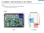
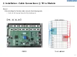
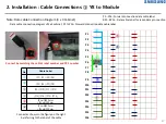
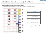
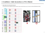
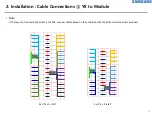
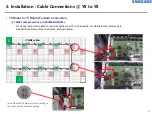
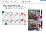
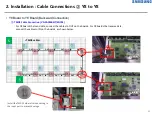
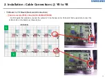
2. Installation : Cable Connections ① Y8 to Module
48
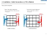
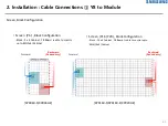
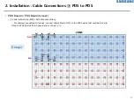
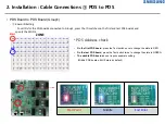
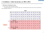
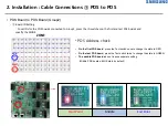
Note: Data cable Connection Diagram (3 x 4 Cabinet)
-
Data cable connection diagram of 3x4 cabinet, RP1 to PR16: Redundancy connection data cable label
No.
Description
⑦
(RP1) (RP2) (RP3) (RP4)
⑧
(RP5) (RP6) (RP7) (RP8)
⑨
(RP9) (RP10) (RP11) (RP12)
⑩
(RP13) (RP14) (RP15) (RP16)
⑦
⑧
RP1
RP2
RP3
RP4
RP5
RP6
RP7
RP8
RP9
RP11
RP12
RP13
RP14
RP15
RP16
⑩
⑨
RP10
Connect as shown in the figure on the right
by referring to the label of the cable
Содержание LH080XPRZAS/PZ
Страница 1: ...Outdoor LED Installation Manual XPR Series Standard Cabinet LH080XPRZAS PZ Rev 0 9 ...
Страница 7: ... Standard Cabinet Outside 1 Product Information Standard Cabinet 7 Front Rear ...
Страница 128: ...4 Control Room Setting System Matrix 128 System Matrix basic function Diagnostics Module 진단 상태 확인 ...

