


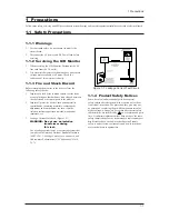


1 Precautions
1-1
1-1-1 Warnings
1.
For continued safety, do not attempt to modify the
circuit board.
2.
Disconnect the AC power and DC Power Jack before
servicing.
1-1-2 Servicing the LCD Monitor
1. When servicing the LCD Monitor Disconnect the AC
line cord from the AC outlet.
2.
It is essential that service technicians have an accurate
voltage meter available at all times. Check the
calibration of this meter periodically.
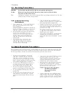
1-1-3 Fire and Shock Hazard
Before returning the monitor to the user, perform the
following safety checks:
1.
Inspect each lead dress to make certain that the leads
are not pinched or that hardware is not lodged between
the chassis and other metal parts in the monitor.
2.
Inspect all protective devices such as nonmetallic
control knobs, insulating materials, cabinet backs,
adjustment and compartment covers or shields,
isolation resistor-capacitor networks, mechanical
insulators, etc.
3.
Leakage Current Hot Check (Figure 1-1):
WARNING: Do not use an isolation
transformer during
this test.
Use a leakage current tester or a metering system that
complies with American National Standards Institute
(
ANSI C101.1, Leakage Current for Appliances
), and
Underwriters Laboratories (
UL Publication UL1410,
59.7
).
Figure 1-1. Leakage Current Test Circuit
1-1-4 Product Safety Notices
Some electrical and mechanical parts have special
safety-related characteristics which are often not evident
from visual inspection. The protection they give may not
be obtained by replacing them with components rated for
higher voltage, wattage, etc. Parts that have special safety
characteristics are identified by on schematics and parts
lists. A substitute replacement that does not have the same
safety characteristics as the recommended replacement part
might create shock, fire and/or other hazards. Product
safety is under review continuously and new instructions
are issued whenever appropriate.
1 Precautions
Follow these safety, servicing and ESD precautions to prevent damage and to protect against potential hazards such as electrical shock.
1-1 Safety Precautions
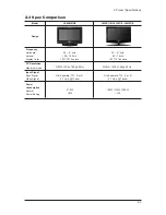
Содержание LE40M91B
Страница 3: ...Contents ...
Страница 4: ...Contents ...
Страница 27: ...4 Troubleshooting 4 4 WAVEFORMS 1 R G B Output Signal of IC500 ...
Страница 29: ...4 Troubleshooting 4 6 2 Digital Output Data of IC500 3 Signal of HDMI Data ...
Страница 31: ...4 Troubleshooting 4 8 WAVEFORMS 4 Tuner_CVBS Output Signal 3 CVBS Output Signal ...
Страница 33: ...4 Troubleshooting 4 10 WAVEFORMS 4 CVBS Output Signal ...
Страница 35: ...4 Troubleshooting 4 12 2 Digital Output Data of IC500 5 Analog Signal Y C to IC500 WAVEFORMS ...
Страница 37: ...4 Troubleshooting 4 14 WAVEFORMS 6 The Signal are Inputed to IC1015 7 DC 12V ...
Страница 68: ...7 Block Diagrams 7 1 7 Block Diagram This Document can not be used without Samsung s authorization ...
Страница 69: ...8 1 8 Wiring Diagrams 8 Wiring Diagram 8 1 LE40M91BX Wiring Diagram ...
Страница 70: ...8 Wiring Diagrams 8 2 8 2 Main Board Layout ...
Страница 74: ...8 Wiring Diagrams 8 6 8 4 Power Board Layout ...
Страница 77: ...8 9 8 Wiring Diagrams ...
Страница 81: ...9 Schematic Diagrams 9 2 9 2 Input Output Schematic Diagram ...
Страница 82: ...9 Schematic Diagrams 9 3 9 3 Input Output Schematic Diagram ...
Страница 83: ...9 Schematic Diagrams 9 4 9 4 Micom Schematic Diagram ...
Страница 84: ...9 Schematic Diagrams 9 5 9 5 SVP PX Schematic Diagram ...
Страница 85: ...9 Schematic Diagrams 9 6 9 6 Application Schematic Diagram ...
Страница 86: ...9 Schematic Diagrams 9 7 9 7 FRCH 100Hz LVDS Schematic Diagram ...
Страница 87: ...9 Schematic Diagrams 9 8 Memo ...
Страница 98: ...12 PCB Diagram 12 1 12 PCB Diagram 12 1 Main PCB Layout ...
Страница 99: ...12 PCB Diagram 12 2 12 2 SMPS PCB Layout ...