iDCS 100
INSTALLATION
TECHNICAL MANUAL
PART 2 JUNE 2002
2.1
PART 2. INSTALLATION OF BASIC KSU AND
EXPANSION CABINET
2.1 UNPACKING AND INSPECTION
After unpacking the KSU, inspect for signs of physical damage. If any damage is
detected, do not attempt to install. Contact SAMSUNG TELECOMMUNICATIONS
AMERICA, Technical Support Department.
Check to see that the KSU carton includes the following items:
!
Key service unit
!
Wall-mount kit consisting of 4 screws
•
Vinyl bag containing cable ties and a battery cable
•
Power cord
•
KSU mounting template
Check to see that the EXPANSION CABINET carton includes the following:
!
Expansion cabinet
!
Vinyl bag with screws and ferrite choke
2.2 KEY SERVICE UNIT INSTALLATION
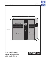
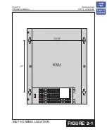
The key service unit (KSU) must be wall-mounted. The KSU should be mounted on a
plywood backboard at least
5
/
8
" thick. Using the installation template or the diagram in
mark the location for four mounting screws. Attach two mounting screws 12
7/8” apart horizontally to the blackboard. Next hang the KSU on the screws and secure
it to the backboard with the remaining two screws
. Tighten all four
screws to secure KSU in place.
2.3 EXPANSION CABINET INSTALLATION
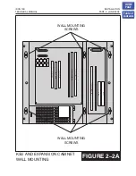
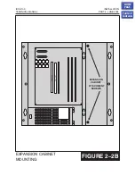
1. Hang the expansion cabinet on the KSU bracket and attach it securely to the
backboard with the two screws supplied
NOTE: When you are adding an expansion cabinet to a system, please
remember to remove the cable access breakout panels BEFORE
attaching the expansion cabinet to the KSU. DO NOT cut the tabs on the
bottom of the breakout-panels as this will leave a sharp edge that can cut
into the cable. Instead bend the panel down out of the way.
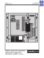
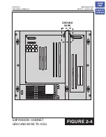
2. Secure the expansion cabinet to the KSU by inserting the two short screws into the
holes on the left of the expansion cabinet
WARNING:
The KSU must be turned off before proceeding. Plugging the cables
into the KSU while it is turned on can result in electric shock and/or
HOME
PAGE
Table of
Contents
Содержание iDCS 100
Страница 31: ...FIGURE 3 4 2 SLI CARD iDCS 100 INSTALLATION TECHNICAL MANUAL PART 3 JUNE 2002 HOME PAGE Table of Contents ...
Страница 37: ...S4BRI CARD iDCS 100 INSTALLATION TECHNICAL MANUAL PART 3 JUNE 2002 FIGURE 3 10 HOME PAGE Table of Contents ...
Страница 41: ...MODEM CARD iDCS 100 INSTALLATION TECHNICAL MANUAL PART 3 JUNE 2002 FIGURE 3 14 HOME PAGE Table of Contents ...
Страница 43: ...ITMC CARD iDCS 100 INSTALLATION TECHNICAL MANUAL PART 3 JUNE 2002 FIGURE 3 16 HOME PAGE Table of Contents ...

