iDCS 100
INSTALLATION
TECHNICAL MANUAL
PART 2 JUNE 2002
2.3
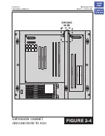
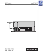
A supplementary equipment grounding conductor shall be installed between the
system and ground that is in addition to the equipment grounding conductor in the
power supply cord.
The supplementary equipment grounding conductor shall not be smaller in size than
the ungrounded branch-circuit supply conductors. The supplementary equipment
grounding conductor shall be connected to the product at the terminal provided, and
shall be connected to ground in a manner that will retain the ground connection when
the product is unplugged from the receptacle. The connection to ground of the
supplementary equipment grounding conductor shall be in compliance with the rules
for terminating bonding jumpers in Part K of Article 250 of the National Electrical Code
ANSI/NFPA 70. Termination of the supplementary equipment grounding conductor is
permitted to be made to building steel, to a metal electrical raceway system, or to any
grounded item that is permanently and reliably connected to the electrical service
equipment ground.
Bare, covered, or insulated grounding conductors are acceptable. A covered or
insulated grounding conductor shall have a continuous outer finish that is either green
or green with one or more yellow stripes.
Failure to provide an adequate ground may cause a safety hazard, confusing trouble
symptoms or even circuit card failure.
WARNING
: Unplug the power cord from the AC outlet before attempting to connect
the ground. Hazardous voltage may cause death or injury. Observe extreme caution
when working with AC power. Remove champ connectors from trunk cards.
What the above paragraphs mean is when conventional analog telephone circuits are
connected to the iDCS 100 system, under fault conditions (i.e., the tip and/or ring
conductor is crossed with a power line, or the circuit is affected by lightning during a
storm), it is possible for hazardous potentials to appear across the tip and ring wiring
coming into the iDCS 100 cabinet(s) from the outside plant (i.e., overhead cables,
buried cables, cable head pedestal). These circuits are provided with both primary and
secondary protection circuitry which will attempt to drain off these high voltages and
currents to earth ground. Obviously, it is important to have a good source of ground
connected to the iDCS 100 system to drain this energy off. Also, certain metallic analog
circuits (e.g., E & M trunks) require a current flow to earth ground to accommodate
normal operating conditions and/or to resolve fault conditions. Again, a good earth
ground source is required by the iDCS 100 system.
The iDCS 100 system has two ground reference points. One point is via the green wire
in the power cord connected to the AC power outlet. This ground connection is
provided to meet local electrical codes when the AC ground is required to be common
with the earth ground. However, this can be disconnected either intentionally or
unintentionally. Consequently, a more permanent ground connection is required by
HOME
PAGE
Table of
Contents
Содержание iDCS 100
Страница 31: ...FIGURE 3 4 2 SLI CARD iDCS 100 INSTALLATION TECHNICAL MANUAL PART 3 JUNE 2002 HOME PAGE Table of Contents ...
Страница 37: ...S4BRI CARD iDCS 100 INSTALLATION TECHNICAL MANUAL PART 3 JUNE 2002 FIGURE 3 10 HOME PAGE Table of Contents ...
Страница 41: ...MODEM CARD iDCS 100 INSTALLATION TECHNICAL MANUAL PART 3 JUNE 2002 FIGURE 3 14 HOME PAGE Table of Contents ...
Страница 43: ...ITMC CARD iDCS 100 INSTALLATION TECHNICAL MANUAL PART 3 JUNE 2002 FIGURE 3 16 HOME PAGE Table of Contents ...

