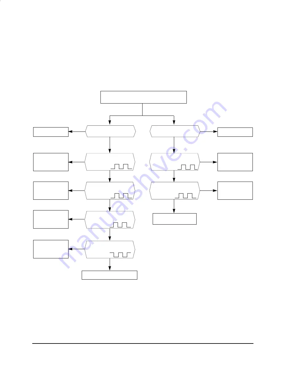
5-2-2 When the assembly panel PCB is not operated
Samsung Electronics
5-3
1) Check points
(1) Is the voltage of the power source normal ?(AC 198V ~ AC 264V)
(2) Is the electric wire in good contact ?(CN71, RY71)
(3) Is the connection of the assembly main PCB, and assembly panel PCB in good contact?
(CN11, CN12)
(4) Is the voltage of +12V normal ?(CN 12 No 1 pin and No 12 pin : +12V±0.5V)
(5) Is the voltage of +5V normal ?(CN12 No 2 pin and No 12 pin : +5V±0.5V)
Check the micom
(IC02) for a short,
and replace it.
Check the micom
(IC02) for a short,
and replace it.
Check the IC03
for a short, and
replace it.
Check the micom
(IC02) for a short,
and replace it.
Normal operation
Check the micom
(IC02) for a short,
and replace it.
Replace the assembly panel PCB
Replace the assembly
panel PCB.
Y
N
Normal operation
N
N
N
N
N
N
Y
Y
Y
Y
Y
Y
Y
Turn off the power, and then turn it on again
five seconds later.
When the LED lamp is
not operated.
When the TACT switch is
not operated.
Is the voltage of the micom
(IC02) No.47~50 port a square
wave?
Is the voltage of the
micom (IC02) No.50port
a square wave?
Is the voltage of the micom
(IC02) No.56,58~63 port a
square wave?
Is the voltage of the
micom(IC02) No.44port a
square wave?
Is the voltage of the
IC03 No. 15~18 a
square wave?
Check the IC04
for a short, and
replace it.
N
Is the voltage of the
IC04 No. 10~16 a
square value?
AW126JB-2 6/27/98 10:40 AM Page 7
Содержание AW127JB
Страница 24: ...Samsung Electronics 6 2 Ass y Control 6 3 1 7 6 5 9 8 13 2 3 4 12 14 10 11...
Страница 30: ...8 1 Samsung Electronics 8 PCB Diagram 8 1 Main PCB ASS Y CODE NO DB93 10502A...
Страница 35: ...10 Schematic Diagrams 10 1 Main PCB Samsung Electronics 10 1 AW126JB 4 6 27 98 11 55 AM Page 1...
Страница 36: ...10 2 Samsung Electronics 10 2 Remote Control...


