Connecting the unit
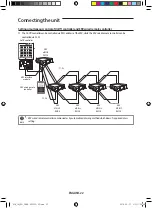
Make sure to disconnect the power cable and power supply before connecting the ERV to other control solutions . If not, it
may cause malfunction due to electrical interference .
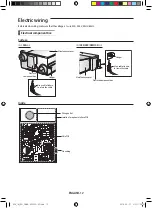
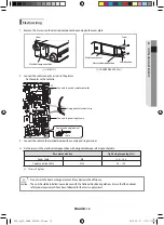
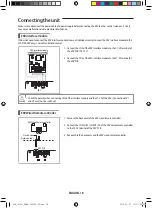
ERV interface module
It does not need to connect the ERV interface module in case of individual control . Connect the ERV interface module to the
MaSTER ERV only, in case of centralized control .
CN4
CN3
RED
CN2
BLK
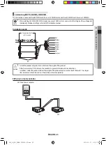
ERV interface module
ERV
1 . Connect the Cn4 of the ERV interface module to the V1, V2 terminal of
the ERV PCB . (DC 12 V)
2 . Connect the Cn3 of the ERV interface module to the F1, F2 terminal of
the ERV PCB .
•
Check the polarity when connecting Cn4 of the interface module and the V1, V2 of the ERV . (Connection of V1
and V2 must not be switched .)
CAUtIoN
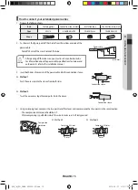
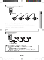
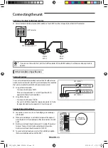
ERV Wired Remote controller
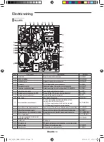
Electric wire
(Field supplied)
ERV Wired Remote controller
ERV PCB
1 . Remove the back cover of the ERV wired remote controller .
2 . Connect the COM a (F3), COM B (F4) of the ERV wired remote controller
to the F3, F4 terminal of the ERV PCB .
3 . Reassemble the back cover and the ERV wired remote controller .
ENGLISH-18
ERV_IM_EN_DB68-05252A-02.indd 18
2016-05-27 오전 11:26:43


