


84
EB 8384-6S EN
a bore with ¼ NPT or G ¼ thread. Custom
-
ary fittings for metal or copper tubing or
plastic hoses can be used.
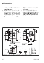
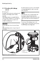
Signal pressure connection
The signal pressure connection depends on
how the positioner is mounted onto the actu-
ator:
−
Type 3277 Actuator
The signal pressure connection is fixed.
−
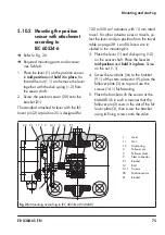
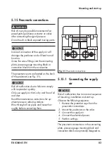
Attachment according to IEC 60534-6
(NAMUR)
For "actuator stem retracts" fail-safe ac-
tion: connect the signal pressure to the
connection on top of the actuator.
For "actuator stem extends" fail-safe ac-
tion: connect the signal pressure to the
connection on the bottom of the actuator.
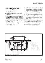
−
Rotary actuators
For rotary actuators, the manufacturer's
specifications for connection apply.
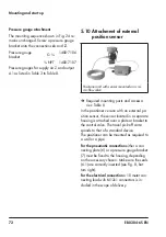
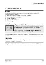
5.15.2 Output signal display
To monitor the supply air and signal pres
-
sure, we recommend mounting pressure
gauges
(see accessories in section 3.8).
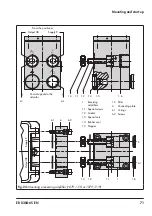
Mounting the pressure gauges:
Î
See section 5.4 and section Fig. 8
5.15.3 Supply pressure
The required supply air pressure depends on
the bench range and the actuator's direction
of action (fail-safe action).
The bench range is written on the nameplate
either as the bench range or signal pressure
range depending on the actuator. The direc-
tion of action is marked FA or FE or by a sym-
bol.
PLOW
is indicated under Code 0 if the sup-
ply pressure is lower than the upper bench
range value determined during plotting of
the valve signature.
Actuator stem extends FA
(AIR TO OPEN)
Fail-close (for globe and angle valves):
Î
Required supply pressure = Upper bench
range value + 0.2 bar, at least 1.4 bar.
Actuator stem retracts FE
(AIR TO CLOSE)
Fail-open (for globe and angle valves):
For tight-closing valves, the maximum signal
pressure pst
max
is roughly estimated as fol-
lows:
pst
max
= F +
d² · π · ∆p
[bar]
4 · A
d
=
Seat diameter [cm]
∆p
= Differential pressure across the
valve [bar]
A =
Actuator area [cm²]
F
= Upper bench range value of the
actuator [bar]
Tip
Note
Содержание TROVIS SAFE 3730-6
Страница 12: ...12 EB 8384 6S EN...
Страница 16: ...16 EB 8384 6S EN...
Страница 22: ...22 EB 8384 6S EN...
Страница 40: ...40 EB 8384 6S EN...
Страница 42: ...42 EB 8384 6S EN...
Страница 82: ...82 EB 8384 6S EN...
Страница 90: ...90 EB 8384 6S EN...
Страница 96: ...96 EB 8384 6S EN...
Страница 132: ...132 EB 8384 6S EN...
Страница 152: ...152 EB 8384 6S EN...
Страница 155: ...EB 8384 6S EN 155...
Страница 156: ...156 EB 8384 6S EN...
Страница 157: ...EB 8384 6S EN 157...
Страница 158: ...158 EB 8384 6S EN...
Страница 159: ...EB 8384 6S EN 159...
Страница 160: ...160 EB 8384 6S EN...
Страница 161: ...EB 8384 6S EN 161...
Страница 162: ...162 EB 8384 6S EN...
Страница 163: ...EB 8384 6S EN 163...
Страница 164: ...164 EB 8384 6S EN...
Страница 165: ...EB 8384 6S EN 165...
Страница 166: ...166 EB 8384 6S EN...
Страница 167: ...EB 8384 6S EN 167...
Страница 182: ...182 EB 8384 6S EN...
Страница 183: ...EB 8384 6S EN 183...