Translation of original instructions
EB 9520 EN
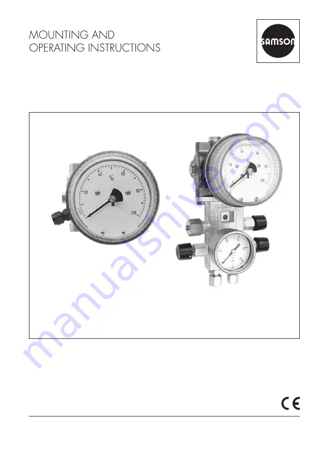
Media 05 with indicating unit and dp cell,
with valve block and pressure gauge for operating pressure (right)
Edition November 2010
Media 05 Differential Pressure and Flow Meter
Страница 1: ...of original instructions EB 9520 EN Media 05 with indicating unit and dp cell with valve block and pressure gauge for operating pressure right Edition November 2010 Media 05 Differential Pressure and...
Страница 2: ...fter sales Service Department aftersalesservice samson de The mounting and operating instructions for the devices are included in the scope of delivery The latest documentation is available on our web...
Страница 3: ...ressure lines 14 3 5 Orifice flange orifice plate assembly 14 4 Accessories 16 4 1 Valve block 16 4 2 Shut off and equalizing valves 16 4 3 Compensation chambers 16 4 4 Accessories for connection 16 5...
Страница 4: ...e caused by external forces or any other external factors Refer to the technical data for limits and fields of application as well as possible uses The Media 05 Differential Pressure and Flow Meter wi...
Страница 5: ...ide the limits defined during sizing and by the technical data Furthermore the following activities do not comply with the intended use Use of non original spare parts Performing maintenance activitie...
Страница 6: ...proper operation and compliance with the safety regulations Operators are obliged to provide these mounting and operating instructions to the operating personnel and to instruct them in proper operat...
Страница 7: ...requirements stipulated by VBG 62 or similar regulations until they are handed over to the manufacturer Otherwise SAMSON does not accept any responsibility Risk of damage to the differential pressure...
Страница 8: ...ce plate creates a force at the measuring diaphragm 1 5 which is opposed by the range springs 1 4 The movement of the measuring diaphragm and lever 1 8 which is proportional to the differential pressu...
Страница 9: ...mber 1 3 Low pressure chamber 1 4 Range springs 1 5 Measuring diaphragm 1 6 Diaphragm plates 1 7 Diaphragm stem 1 8 Lever 1 9 Flexible disk Housing of indicating unit 2 1 Gear segment 2 2 Pointer mech...
Страница 10: ...ale division for any linear measured variable for measured variables based on equations curve or table Characteristic Characteristic linear to differential pressure scale linear to tank content Deviat...
Страница 11: ...rox 2 6 kg without valve block 4 6 kg with valve block Materials Version Standard version Housing Brass CW617N or CrNi steel Measuring diaphragm and seals ECO 2 Springs diaphragm plates functional par...
Страница 12: ...everse installation can only be used when there is no other possibility particularly for steam measurements Refer to VDE VDI 3512 Sheet 1 for details 3 3 Media 05 indicating unit Make sure that the hi...
Страница 13: ...embly Compensation chamber Standard Standard Installation standard Separation chamber Reverse Reverse Measurement of liquids Measurement of steam Measurement of gases h H z h H h K H Y H Measuring ran...
Страница 14: ...w on the orifice plate Unobstructed pipe sections are required upstream and downstream of the orifice plate assembly For the orifice tubes de livered by SAMSON these section are ensured by the weld on...
Страница 15: ...tallation Location of the differential pressure lines on the orifice plate assembly For steam For gas For liquids Type 90 Orifice Flange Inlet 20 to 50 x d Outlet 5 x d 65 d Fig 3 Orifice flange orifi...
Страница 16: ...t off valves as well as the bypass valve equalizing valve can also be installed as illustrated in Fig 5 4 3 Compensation chambers Compensation chambers that establish a constant liquid column are requ...
Страница 17: ...valve Shut off valves Holes for lead seal wires Shut off valves Test connection Liquid level measurement Fig 4 SAMSON valve block Flow rate measurement 1 Shut off valves 2 Equalizing valve To the ind...
Страница 18: ...late 1 Slowly open the high pressure line 2 Close the equalizing valve or bypass of the valve block 3 Open the low pressure line NOTICE 4 Wait a while Open both vent screws of the dp cell one after th...
Страница 19: ...the shut off valve in the low pres sure line to allow the pressures to equal ize in the dp cell The pointer must indicate zero If this is not the case undo the dial screws and turn the dial it can be...
Страница 20: ...pressure to the high pressure mea suring chamber until the pointer indi cates 100 while the low pressure con nection is open Read off the adjusted pressure value at the pressure gauge It corresponds...
Страница 21: ...Class 0 1 pressure gauge 1 Screws 2 Cover plate 3 Fastening screw 4 Measuring unit frame 5 Dial screws Recess for screwdriver 5 4 3 2 1 Supply air reducing sta tion with oil filter and test pressure...
Страница 22: ...he listed maximum values in the table apply concerning the connection of proximity switches to certified intrinsically safe circuits in the type of protection Ex ia IIC T6 PTB 00 ATEX 2049 X Type 1 Ty...
Страница 23: ...ifica tions 1 Connect the device to a switching ampli fier as described in section 7 1 2 Apply a pressure to the high pressure connection of the dp cell which corre sponds to the desired switching poi...
Страница 24: ...contact unit 2 onto the unit frame plate 3 from the right so that the metal tags reach into the proximity switches without touching the contacts 5 Fasten the contact unit 2 to the measur ing unit fra...
Страница 25: ...s 1 PCB 2 Contact unit 3 Measuring unit frame 4 1 Connecting cable A1 4 2 Connecting cable A2 5 Slotted head screws 6 Phillips screw 8 Cable gland Positioning notch 3 6 1 8 4 1 5 A1 2 A2 5 4 2 51 52 4...
Страница 26: ...EB 9520 EN Dimensions 8 Dimensions 31 60 212 5 110 _ Pressure gauge connection G LH with coupling sleeve G for pressure gauge NG 100 and 12x2 O ring as well as for G for pressure gauge NG 63 with G se...
Страница 27: ...EB 9520 EN 27 Dimensions 200 117 25 64 26 43 36 58 26 103 129 5 80 SW14 G Valve block when mounted upside down Pipe mounting...
Страница 28: ...4 117 158 5 25 17 5 52 30 35 8 6 30 Drill pattern for wall panel mounting Center of the indicator unit Two 8 5 mm holes for fastening at the back of the dp cell M8 screws Two 8 5 mm holes for fastenin...
Страница 29: ...EB 9520 EN 29...
Страница 30: ......
Страница 31: ......
Страница 32: ...2019 10 23 English SAMSON AKTIENGESELLSCHAFT Weism llerstra e 3 60314 Frankfurt am Main Germany Phone 49 69 4009 0 Fax 49 69 4009 1507 samson samson de www samson de EB 9520 EN...