background image

11-2 


EB 8055 EN

Removal

actuator springs is transmitted to the 
actuator stem and the stem (9).


Î

First remove the actuator from the valve 
or ensure it cannot transmit any forces to 
the actuator stem before removing the 
anti-rotation fixture on the plug stem.

Before removing the valve, make sure the fol-

lowing conditions are met:


The control valve is put out of operation 
(see the 'Decommissioning' section).

11.1 

Removing the valve from 

the pipeline

1.  Support the valve to hold it in place 

when separated from the pipeline (see 

the 'Shipment and on-site transport' sec-

tion).

2. 

Unbolt the flange joint.

3.  Remove the valve from the pipeline (see 

the 'Shipment and on-site transport' sec-

tion).

11.2 Removing the actuator 

from the valve

See associated actuator documentation.

Содержание 3253

Страница 1: ...Translation of original instructions EB 8055 EN Edition January 2021 Type 3253 Valve DIN version In combination with an actuator e g a Type 3271 or Type 3277 Pneumatic Actuator...

Страница 2: ...st you in mounting and operating the device safely The instructions are binding for handling SAMSON devices The images shown in these instructions are for illustration purposes only The actual product...

Страница 3: ...sions 3 3 3 3 Additional fittings 3 3 3 4 Accessories 3 4 3 5 Technical data 3 4 4 Shipment and on site transport 4 1 4 1 Accepting the delivered goods 4 1 4 2 Removing the packaging from the valve 4...

Страница 4: ...subject to wear 9 6 9 4 1 Standard version 9 6 9 4 2 Version with insulating section 9 13 9 4 3 Sequence of packing parts 9 14 9 5 Ordering spare parts and operating supplies 9 16 10 Decommissioning...

Страница 5: ...or damage caused by external forces or any other external factors Refer to the technical data and nameplate for limits and fields of application as well as possible uses Reasonably foreseeable misuse...

Страница 6: ...or control signal failure depends on the actuator used see associated actuator documentation When the valve is combined with a SAMSON Type 3271 or Type 3277 Pneumatic Actuator the valve moves to a ce...

Страница 7: ...ting personnel Operating personnel must read and understand these mounting and operating instructions as well as the referenced documents and observe the specified hazard statements warnings and cauti...

Страница 8: ...e of very high concern on the candidate list of the REACH regulation Information on safe use of the part affected u www samsongroup com About SAMSON Material Compliance REACH If a device contains a su...

Страница 9: ...Install the control valve in such a way that vent openings are not located at eye level and the actuator does not vent at eye level in the work position Use suitable silencers and vent plugs Wear eye...

Страница 10: ...s medium from all the plant sections affected and the valve Wear protective clothing safety gloves respiratory protection and eye protection Risk of personal injury through incorrect operation use or...

Страница 11: ...k of valve damage due to the use of unsuitable lubricants The lubricants to be used depend on the valve material Unsuitable lubricants may cor rode and damage surfaces Only use lubricants approved by...

Страница 12: ...Warning Meaning of the warning Location on the device Warning against moving parts There is a risk of injury to hands or fingers through the stroking movement of the actuator and plug stem if they are...

Страница 13: ...seal ME metal HA carbide metal ST metal base material with Stellite facing KE ceramic PT PTFE soft seal PK PEEK soft seal 13 Seat code trim material on request 14 Pressure balancing DIN D ANSI JIS B V...

Страница 14: ...m material This seat code is specified on the nameplate 2 4 Label when an adjustable packing is installed An instructional label is affixed to the valve when an adjustable packing is installed see Fig...

Страница 15: ...ed by the arrow A rise in signal pressure causes the force acting on the diaphragm in the actuator to increase The springs are compressed Depending on the selected direction of action the actuator ste...

Страница 16: ...d principle of operation Fig 3 1 Type 3253 Valve as mixing valve with Type 3271 Pneumatic Actuator Fig 3 2 Type 3253 Valve as diverting valve AB A B AB A B A26 27 17 A7 A8 A4 A10 20 14 225 5 4 36 1 4...

Страница 17: ...seal to be fitted to the stan dard valve version Actuators In these instructions the preferable combina tion with a SAMSON Type 3271 or Type 3277 Pneumatic Actuator is described The pneumatic actuato...

Страница 18: ...act pressure gauge an outlet to an open vessel or an inspection glass Safety guard For operating conditions that require in creased safety e g in cases where the valve is freely accessible to untraine...

Страница 19: ...essures acc to pressure temperature diagrams see Information Sheet uT 8000 2 Body without insulating sec tion 10 to 220 C Up to 350 C with high temperature packing Body with insulating section or bell...

Страница 20: ...430 550 Height H4 PN 10 to 40 152 152 164 217 222 242 315 PN 63 to 160 PN 250 to 400 186 186 195 251 288 348 445 H8 for actuator 350 cm 240 240 240 240 240 240 700 cm 240 240 240 240 240 240 418 1400...

Страница 21: ...r with 1000 cm actuator area and larger u T 8310 3 for Type 3271 Actuator with 1400 60 cm actuator area Note Valve DN 200 250 300 400 500 H8 for actuator 350 cm 700 cm 418 418 1400 60 cm 418 418 503 5...

Страница 22: ...3 8 EB 8055 EN...

Страница 23: ...ta section 4 2 Removing the packaging from the valve Observe the following sequence Do not open or remove the packaging until immediately before lifting to install the valve into the pipeline Leave th...

Страница 24: ...ings to the actuator handwheel or any other parts Observe lifting instructions see sec tion 4 3 2 A swivel hoist can be screwed into SAMSON actuators with a female thread on the top diaphragm case in...

Страница 25: ...ke sure the slings can be removed from the valve once it has been installed into the pipeline Prevent the control valve from tilting or tipping over Do not leave loads suspended when in terrupting wor...

Страница 26: ...otect the control valve against external influences e g impact Secure the valve in the stored position against slipping or tipping over Do not damage the corrosion protection paint surface coatings Re...

Страница 27: ...EB 8055 EN 4 5 Shipment and on site transport...

Страница 28: ...4 6 EB 8055 EN...

Страница 29: ...alve or to perform service work on them In heating or cooling applications the valve can be installed in the flow pipe or return flow pipe see Fig 5 1 Mounting position Generally we recommend installi...

Страница 30: ...ion FA Actuator stem extends FE Actuator stem retracts In heating applications with FA the heating medium flow is shut off in the fail safe position in cooling applications with FE cooling is maintain...

Страница 31: ...ntrol valves with insulat ing section or bellows seal up to the bon net flange of the valve body for medium temperatures below 0 C and above 220 C If the insulating section is insu lated it will not f...

Страница 32: ...es of the yoke 3 Fasten the yoke 3 using the castellated nut 92 4 Fasten the hanger 83 and warning la bel 255 if applicable to the yoke us ing the screws 82 5 Position the travel indicator scale 84 on...

Страница 33: ...wing There is a nominal clearance of 0 5 to 1 mm between the sliding washers and their contact surface on the yoke on each side see detailed view Y in Fig 5 3 The anti rotation fixture does not get st...

Страница 34: ...10 310 92 84 85 255 Legend 3 Yoke 82 Screws 83 Hanger 84 Travel indicator scale 85 Screws 92 Castellated nut 255 Warning label 310 Ball bearing Plug stem Fig 5 2 Overview of yoke assembly with travel...

Страница 35: ...1 301 309 309 9 303 304 114 Y 1 0 0 5 Y 1 0 0 5 Legend 9 Stem 114 Lubricant Gleitmo 1763 V 301 Clamps 303 Screws 304 Washers 309 Sliding washers Plug stem Fig 5 3 Overview of anti rotation fixture ass...

Страница 36: ...incorrectly applied lubricant Do not apply any lubricant to the threads of the clamps 301 or the plug stem 6 Position the clamps 301 and stem 9 on the plug stem according to Table 5 3 and tighten scr...

Страница 37: ...82 Screws 83 Hanger 84 Travel indicator scale 92 Castellated nut 255 Warning label 302 Holder 306 Screws 308 Washers 83 82 84 92 3 306 308 302 255 Plug stem Fig 5 4 Overview of yoke assembly with trav...

Страница 38: ...01 301 309 309 304 303 9 114 Y Y 1 0 0 5 1 0 0 5 Legend 9 Stem 114 Lubricant Gleitmo 1763 V 301 Clamps 303 Screws 304 Washers 309 Sliding washers Plug stem Fig 5 5 Overview of anti rotation fixture as...

Страница 39: ...7 5 103 5 82 5 34 5 30 1000 1400 60 15 100 60 136 105 30 75 45 121 120 1400 120 30 75 90 231 195 2800 30 100 120 231 195 DN 125 to 150 NPS 6 Standard version 355 700 750 15 0 0 263 5 67 5 192 87 48 10...

Страница 40: ...0 75 90 221 195 61 100 60 0 0 308 255 61 185 60 50 60 191 225 48 76 2800 5600 30 0 0 191 225 48 76 30 100 120 221 195 61 100 60 0 0 308 255 61 185 60 75 90 191 225 48 76 DN 250 NPS 10 seat bore 250 an...

Страница 41: ...EB 8055 EN 5 13 Installation H G H F H N H O H L H T H K H I Ball bearings standard version only Fig 5 6 Dimensional drawing with mounting dimensions for Types 3271 and 3277 Pneumatic Actuators...

Страница 42: ...y the long bolts protruding from the bottom of the actu ator Before starting any work on the actuator relieve the compression from the pre loaded springs see associated actuator documentation Dependin...

Страница 43: ...eed as de scribed in the associated actuator docu mentation b Aligning the travel indicator scale After mounting the actuator the travel indi cator scale must be aligned To do so align 0 on the travel...

Страница 44: ...to incorrect opening of pressurized equipment or components Valves and pipelines are pressure equipment that may burst when handled incorrectly Flying projectile fragments or the release of process me...

Страница 45: ...aded springs Actuators with preloaded springs are under tension They can be identified by the long bolts protruding from the bottom of the actu ator Before starting any work on the actuator relieve th...

Страница 46: ...t seal properly contact our after sales service 5 4 2 Travel motion The movement of the actuator stem must be linear and smooth Apply the maximum and minimum con trol signals to check the end position...

Страница 47: ...or pneumatic valve accessories not fitted with noise reducing fittings Both can damage hearing Wear hearing protection when working near the valve Crush hazard arising from actuator and plug stem mov...

Страница 48: ...sizing requirements see information under In tended use in the Safety instructions and measures section Start up putting the valve back into opera tion 1 Allow the valve to cool down or warm up to rea...

Страница 49: ...e accessories not fitted with noise reducing fittings Both can damage hearing Wear hearing protection when working near the valve Crush hazard arising from actuator and plug stem moving Do not insert...

Страница 50: ...e handwheel of valves with actuators fitted with a handwheel must be in the neutral po sition during normal operation 7 2 Manual operation Valves with actuators fitted with a handwheel can be manually...

Страница 51: ...pression See associated actuator documentation Diaphragm in the actu ator defective See associated actuator documentation Signal pressure too low Check the signal pressure Check the signal pressure li...

Страница 52: ...t Check the flange joint Replace gasket at the flanged joint see the Servicing section or contact our after sales service 1 See the Markings on the device section Contact our after sales service for m...

Страница 53: ...s well as the valve Risk of burn injuries due to hot or cold components and pipeline Valve components and the pipeline may be come very hot or cold Risk of burn injuries Allow components and pipelines...

Страница 54: ...ified by the long bolts protruding from the bottom of the actu ator Before starting any work on the actuator relieve the compression from the pre loaded springs see associated actuator documentation R...

Страница 55: ...test plan Our after sales service can support you in drawing up an inspection and test plan for your plant Note Tip We recommend the following inspection and testing which can be performed while the p...

Страница 56: ...ly Tighten the connections of the valve accessories Check to ensure that the actuator and plug stem move smoothly Version with adjustable packing 1 tighten the packing correctly see information under...

Страница 57: ...e is DN 100 The valve does not have a balanced plug The valve does not have a flow divider The valve does not have a bellows seal The standard or ADSEAL packing is installed in the valve To replace pa...

Страница 58: ...5 and sleeves 75 from the plug stem 3 Unscrew the castellated nut 92 and take the yoke assembly 60 off the bonnet 2 4 Undo the body nuts 14 gradually in a crisscross pattern 5 Remove the bonnet 2 and...

Страница 59: ...wn the bonnet 2 with the top body nuts 14 Tighten the nuts gradually in a crisscross pattern Observe tightening torques 23 Screw in the threaded bushing 8 and tighten it 24 Loosely screw the lock nut...

Страница 60: ...lly clean the sealing faces in the valve body 1 and on the bonnet 2 11 Unscrew the stem connector nut 9 and lock nut 10 from the plug stem 12 Unscrew the threaded bushing 8 13 Pull the plug stem 36 ou...

Страница 61: ...15 Packing 17 Body gasket 20 Seat body 36 Plug stem 60 Yoke assembly 75 Sleeve 76 Sleeve 92 Castellated nut 225 Nut A7 Actuator stem A8 Ring nut A26 27 Stem connector clamps AB A B A26 27 17 A7 A8 20...

Страница 62: ...at the bottom end of the plug stem while holding the stem connector nut 9 stationary c Multi piece body Diverting valve 1 DN 15 to 50 unscrew the nut 225 from the bottom end of the plug stem while ho...

Страница 63: ...ool 17 Apply a suitable lubricant to the thread and the sealing cone of the new seats 18 Screw in the top and bottom seat 4 Observe tightening torques 19 Insert a new top gasket 17 into the body 20 Ap...

Страница 64: ...he body 30 Place the seat body 20 onto the body 1 and fasten down it with the bottom body nuts 14 Tighten the nuts gradual ly in a crisscross pattern Observe tight ening torques 31 Place the sleeves 7...

Страница 65: ...ions with in sulating section are replaced according to the same principle as for the standard ver sion Proceed as described in section 9 4 1 The insulating section 21 is installed in stead of the bon...

Страница 66: ...her assembly b ADSEAL packing 1 Carefully slide the packing parts over the plug stem into the packing chamber us ing a suitable tool Observe the proper sequence see Fig 9 6 2 Slide the seals 15 2 over...

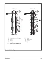
Страница 67: ...eaded bushing packing nut 11 Spring 12 Washer 15 Packing 15 1 Spacer ring with retaining ring 15 2 Seals 16 Packing rings 18 Bushing 19 Spacer 16 8 12 12 11 19 16 15 2 15 15 1 19 12 12 8 12 12 11 19 1...

Страница 68: ...nearest SAMSON subsidiary or SAMSON s After sales Service for infor mation on spare parts lubricants and tools Spare parts See Annex for details on spare parts Lubricant See document u AB 0100 for det...

Страница 69: ...clothing and safety gloves Risk of personal injury due to pressurized components and process medium being discharged Do not loosen the screw of the test con nection while the valve is pressurized Ris...

Страница 70: ...e valve While working on the valve residual me dium can flow out of the valve and depend ing on its properties cause personal injury e g chemical burns Wear protective clothing safety gloves respirato...

Страница 71: ...tored energy in the actuator e g spring compression See associated actuator documentation Risk of personal injury due to residual process medium in the valve While working on the valve residual medium...

Страница 72: ...lve make sure the fol lowing conditions are met The control valve is put out of operation see the Decommissioning section 11 1 Removing the valve from the pipeline 1 Support the valve to hold it in pl...

Страница 73: ...fter sales Service 2 Send an e mail u retouren samsongroup com to register the return shipment including the following information Type Article number Configuration ID Original order Completed Declara...

Страница 74: ...12 2 EB 8055 EN...

Страница 75: ...EB 8055 EN 13 1 Disposal 13 Disposal Observe local national and internation al refuse regulations Do not dispose of components lubricants and hazardous substances together with your household waste...

Страница 76: ...13 2 EB 8055 EN...

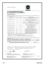
Страница 77: ...42 EC for Types 3253 1 and 3253 7 Control Valves on page 14 4 Declaration of incorporation in compli ance with Machinery Directive 2006 42 EC for the Type 3253 Valve with other actuators other than Ty...

Страница 78: ...L1 L21 ANSI body of cast iron NPS 2 to NPS 4 fluids G2 L1 L21 Dreiwegeventil Three way valve V2001 3323 DIN Geh use GG DN 65 100 Fluide G2 L1 L21 DIN body of cast iron DN 65 100 fluids G2 L1 L21 Dreiw...

Страница 79: ...EB 8055 EN 14 3...

Страница 80: ...14 4 EB 8055 EN...

Страница 81: ...EB 8055 EN 14 5...

Страница 82: ...14 6 EB 8055 EN...

Страница 83: ...ation fixture 60 1 Anti rotation fixture 60 2 Holder 60 10 Bushing 60 11 Bushing 60 12 Hex screw 60 13 Hex screw 60 14 Washer 60 15 Threaded pin 60 16 Ball bearings anti rotation fixture 60 17 Slider...

Страница 84: ...15 2 EB 8055 EN 14 2 4 7 36 5 5 4 13 17 1 91 40 12 12 11 19 16 3 82 84 83 9 10 92 15 60 Type 3253 up to DN 40 Mixing diverting service Single piece body...

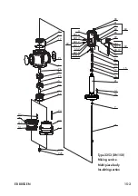
Страница 85: ...4 93 16 12 19 12 16 8 225 224 14 117 20 13 17 73 20 14 4 76 5 75 5 76 15 60 60 60 13 60 12 60 11 60 2 60 10 3 60 14 81 83 84 85 92 9 60 1 60 15 10 80 36 60 60 16 60 17 Type 3253 DN 150 Mixing service...

Страница 86: ...3 17 4 60 13 60 12 60 11 60 2 60 10 3 60 14 81 83 84 85 92 9 60 1 60 15 10 80 5 231 230 36 39 7 101 43 33 94 32 42 12 16 19 12 11 8 37 76 76 75 5 15 22 14 93 33 39 60 60 60 60 16 60 17 Type 3253 DN 15...

Страница 87: ...iaries The addresses of SAMSON AG its subsid iaries representatives and service facilities worldwide can be found on our website www samsongroup com or in all SAMSON product catalogs Required specific...

Страница 88: ...15 6 EB 8055 EN...

Страница 89: ......

Страница 90: ......

Страница 91: ......

Страница 92: ...2021 10 14 English SAMSON AKTIENGESELLSCHAFT Weism llerstra e 3 60314 Frankfurt am Main Germany Phone 49 69 4009 0 Fax 49 69 4009 1507 samson samsongroup com www samsongroup com EB 8055 EN...

Отзывы: