9-6
EB 8055 EN
Servicing
9.3 Installing the valve after
service work
1.
Mount actuator. See associated actuator
documentation and the 'Installation' sec
-
tion.
2.
Adjust lower or upper signal bench
range. See associated actuator docu
-
mentation.
3.
Install the valve into the pipeline (see the
'Installation' section).
4. Put the control valve back into operation
(see the 'Start-up' section). Observe the
requirements and conditions for start-up
or putting the valve back into operation.
9.4
Exchanging parts subject
to wear
Î
Before performing any service work,
preparations must be made to the control
valve (see section 9.2).
Î
After all service work is completed, check
the control valve before putting it back
into operation (see 'Testing the installed
valve' in the 'Installation' section).
9.4.1
Standard version
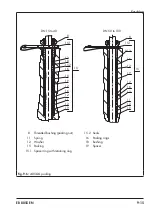
a) Single-piece body
1.
Unscrew the nut (40) from the bottom
end of the plug stem while holding the
stem connector nut (9) stationary.
2.
Remove the bottom plug (5) and sleeves
(75) from the plug stem.
3.
Unscrew the castellated nut (92) and take
the yoke assembly (60) off the bonnet
(2).
4. Undo the body nuts (14) gradually in a
crisscross pattern.
5. Remove the bonnet (2) and plug stem
(36) together with the top plug (5) from
the body (1).
6. Remove the gasket (17). Carefully clean
the sealing faces in the valve body (1)
and on the bonnet (2).
7.
Unscrew the stem connector nut (9) and
lock nut (10) from the plug stem.
8. Unscrew the threaded bushing (8).
9.
Pull the plug stem (36) together with the
top plug (5) out of the bonnet (2).
10.
Pull the entire packing out of the packing
chamber using a suitable tool.
11.
Make sure that the guide bushing (7) is
not damaged. If necessary, replace the
guide bushing using a suitable tool.
12.
Unscrew the top plug (5) from the plug
stem (36).
13. Unscrew the bottom seat (141) and top
seat (4) using a suitable tool.
14. Apply a suitable lubricant to the thread
and the sealing cone of the new seats.
15. Screw in the top seat (4) and bottom seat
(141). Observe tightening torques.
16. Insert a new gasket (17) into the body.
17. Apply a suitable lubricant to the plug
stem (36).
18. Screw the new top plug (5) onto the plug
stem (36).
A
B
AB
141
75
40
17
17
Body gasket
40
Nut
75
Sleeve
141
Bottom seat
Fig. 9-1:
Single-piece body
Содержание 3253
Страница 22: ...3 8 EB 8055 EN...
Страница 27: ...EB 8055 EN 4 5 Shipment and on site transport...
Страница 28: ...4 6 EB 8055 EN...
Страница 74: ...12 2 EB 8055 EN...
Страница 76: ...13 2 EB 8055 EN...
Страница 79: ...EB 8055 EN 14 3...
Страница 80: ...14 4 EB 8055 EN...
Страница 81: ...EB 8055 EN 14 5...
Страница 82: ...14 6 EB 8055 EN...
Страница 88: ...15 6 EB 8055 EN...
Страница 89: ......
Страница 90: ......
Страница 91: ......


