


Index revision : A
37
7145
10. Communication with the PLC in CAN
10.1. Characteristics
In CAN mode a PLC manages the display and/or control of the data of the INOBOX module.
It is necessary to configure the address of the Inobox and the communication speed (from 0 to
7) using the setting screen.
10.2. Data exchange
10.2.1. From CAN to the Inobox module
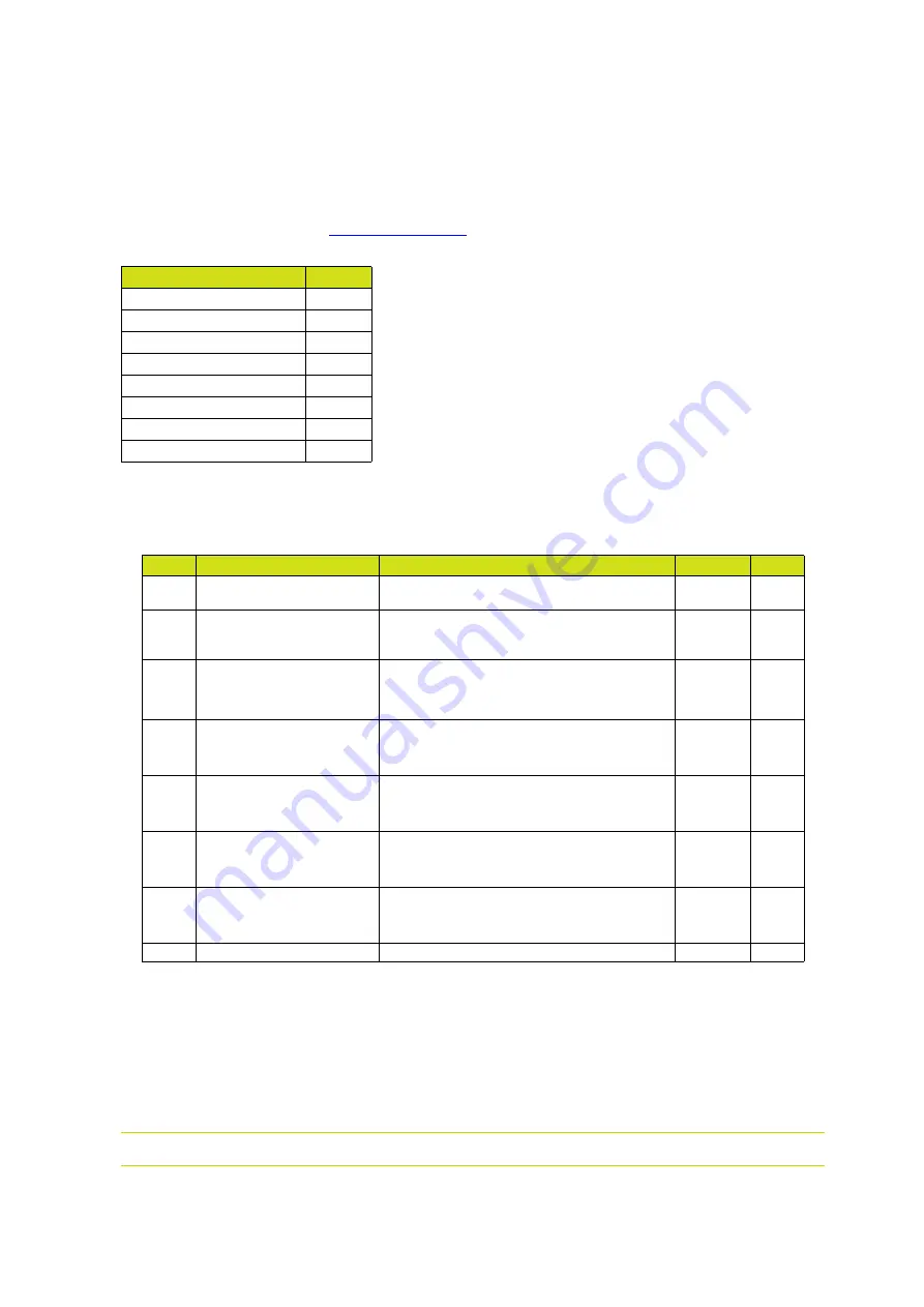
8 bytes are exchanged from a CAN module to the Inobox
Speed in Kbits/s
10
0
20
1
50
2
100
3
125
4
250
5
500
6
1000
7
Byte
Label
Description
Unit
Max.
0
CAN Command
Commands requested by the CAN (see the
detailed description hereafter)
-
1
CAN Current Setpoint
Current setpoint requested by the CAN.
This setpoint is applied only if the CAN_Control
mode is active and the HV trigger is activated
µA
110
2
CAN Voltage Setpoint
High voltage setpoint requested by the CAN.
This setpoint is applied only if the CAN_Control
mode is active and the HV trigger is activa-
ted.
kV
100
3
CAN Injection Setpoint
Injection setpoint requested by the CAN.
This setpoint is applied only if the CAN_Control
mode is active and the HV trigger is activa-
ted.
Point
100
4
CAN Dilution Setpoint
Dilution setpoint requested by the CAN.
This setpoint is applied only if the CAN_Control
mode is active and the HV trigger is activa-
ted.
Point
100
5
CAN Blowing Setpoint
Blowing setpoint requested by the CAN.
This setpoint is applied only if the CAN_Control
mode is active and the HV trigger is activa-
ted.
Point
30
6
CAN Fluidisation Setpoint
Fuidisation setpoint requested by the CAN.
This setpoint is applied only if the CAN_Control
mode is active and the HV trigger is activa-
ted.
Point
50
7
Spare