57
Tel: 886.2.2175 2930 Email: [email protected]
Position zone
Set where the trigger output may occur and the width of trigger pulse.
4.7.
Selecting Data Format and Scale
Data format refers to the way the Analyzer graphically displays Measure data. The data format most suitable for understanding the
property of measured piece shall be selected during the Measure. This section introduces 9 data formats and how to set the scale so
as to better display measuring information.
4.7.1.
Data Format
4.7.1.1.
Rectilinear coordinate format
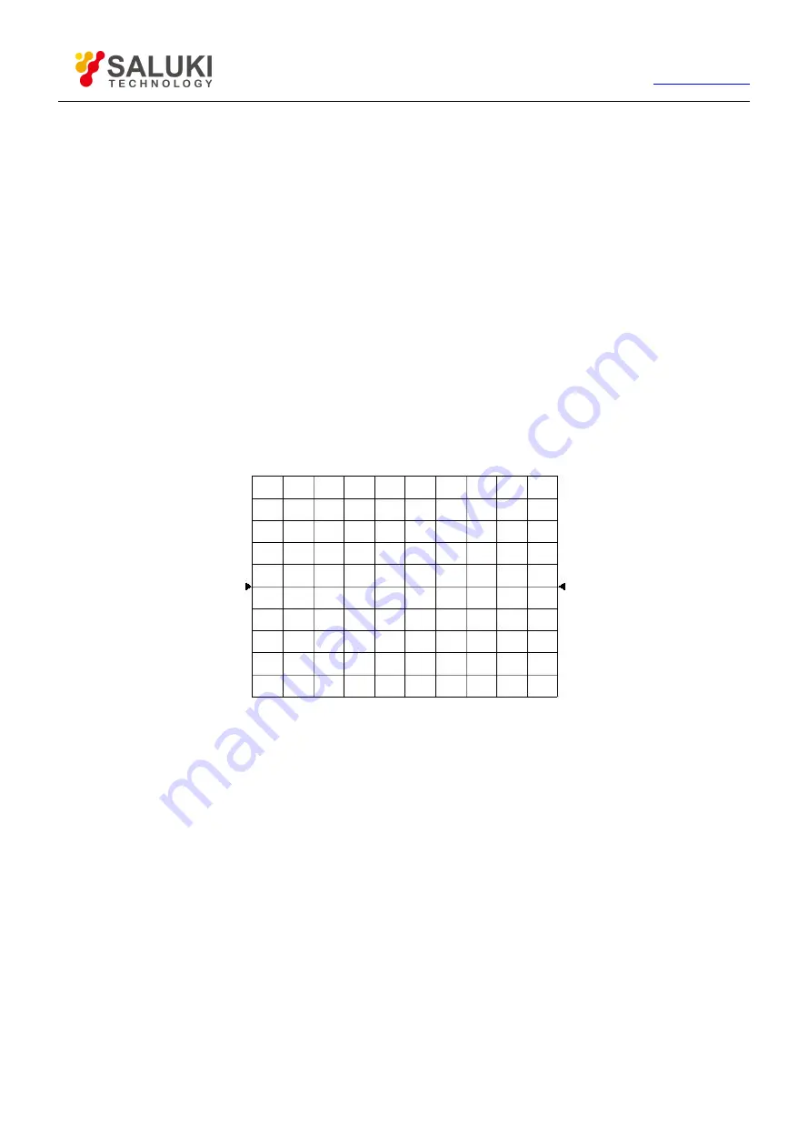
7 among the 9 data formats display measuring data information in rectilinear coordinate, which is also called Descartes format, X/Y
format or linear grid format. This is most suitable for displaying frequency response information of the measured piece. Rectilinear
coordinate will display the following information:
By default, X axis displays stimulus value in linear scale (frequency, power or time).
Y axis displays the corresponding response value at different stimulus values.
Fig. 4-23 Rectilinear Coordinate Format
The 7 data formats displayed in rectilinear coordinate are:
Log-magnitude format
Display magnitude information (without phase information).
Y axis unit: the unit is dB when ratio is measured and it is dBm when non-ratio power is measured.
Suitable typical Measure: return loss, insertion loss and gain.
Phase format
Display phase information (without magnitude information).
Y axis unit: phase (degree).
Suitable typical Measure: linear phase deviation.
Group delay format
Display the transfer time of signal passing through the measured piece.


