salmson NEX Скачать руководство пользователя страница 46

  ENGLISH  


18 

9.3.2


RE-ASSEMBLY 

To assemble the pump consult the sectional drawings. 
 
Ensure  threads,  gasket  and  O-ring  mating  faces  are  clean.  Apply 
thread sealant to non-face-sealing pipe thread fittings. 


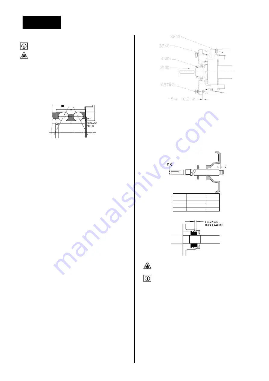
9.3.2.1 ASSEMBLY OF BEARING  BRACKET AND SHAFT 

1. Clean the inside of the bearing housing 3200, bearing carrier 3240 and 
bores for bearings. 
2. Attach bearing housing support foot 3134. 
3. Fit the thrust ball bearing 3013 on to shaft 2100. 
The  double  row  thrust  bearing  must  not  have  a  filling  slot,  as  such 
bearings are limited to taking thrust in only one direction. If the pair of 
angular contact thrust bearings are to be fitted, these must be mounted 
back-to-back, as shown below : 


Grease retainer (clearance type) is only fitted on grease lubricated units. 
 
The  following  methods  are  recommended  to  set  the  bearings onto  the 
shaft: 

1

rst

 method

 : Use a hotplate, hot bath, oven or induction heater to heat 

the  bearing  race  so  it  can  easily  be  placed  in  position  then  allowed  to 
shrink  and  grip  the  shaft.  It  is  important  that  the  temperature  is  not 
raised above 100 ºC. 

2

nd

 method

 : Press the bearing onto the shaft using equipment that can 

provide  a  steady,  even  load  to  the  inner  race.  Take  care  to  avoid 
damaging the bearing and shaft. 
 
4.  With  bearings  at  ambient  temperature,  screw  on  the  self-locking 
bearing locknut 3712.1 (with its polyamide insert facing away  from the 
bearing) until tight. 
5. With the double row thrust bearing place the bearing circlip 6544 over 
the shaft, with the tapered face facing the impeller end. 
6. With the heavy duty thrust bearing option, the lock nut 3712.2, 3864 
grease retainer and 3712.2 if grease lubricated, should be placed on the 
shaft with the larger diameter end facing the impeller end. 
7. Fit pump radial ball bearing 3011 onto the shaft using Method 1 or 2 
above. 
8. With the NUP roller bearing option, the loose  ring should be against 
the shaft shoulder. 
9. Fit O-ring 4610.2 on the bearing carrier. Lightly lubricate the bearing 
carrier bore and O-ring. 
10.  If  a  labyrinth  seal  is  used  make  sure  that  the  oil  port  is  positioned 
downward (if any question ask manufacturer). 
11. Ensure the shaft keyway edges are free of burrs. During installation, 
use shimming or tape over the keyway to avoid damaging the drive side 
bearing seals. 
12. On grease lubricated pumps, ¾ fill the space between bearing races 
with the appropriate grease. 
13. Slide the bearing carrier 3240 onto the shaft/ bearing assembly and 
insert inner circlip 6544 into the carrier groove or screw up the bearing 
locking ring. 
14. Check shaft 2100 for free rotation. 
15.  Fit  the  labyrinth  ring  4330  into  the  bearing  housing  3200  ensuring 
the drain hole faces the bearing and is at the 6 o'clock position. 
16. Install the shaft assembly into the bearing housing 3200 until the gap 
is approximately 5 mm (0.2 in.). 
17. Fit the bearing carrier screws 6570.1 but do not tighten 


18. Press drive side v-ring 4305 and pump side liquid deflector 2540 onto 
shaft  2100  where  applicable.  The  V-ring  type  shall  be  fitted  with  light 
contact with the bearing carrier 3240. 
19.  The  pump  side  deflector  2540  (this  feature  is  integral  with  some 
proprietary  labyrinth seals)  should only  be  set  in its final  position after 
setting the shaft axial position. 
20. Temporarily fit the cover 1220 to the power-end.  The cover, above 
125  size,  is retained by  studs 6580  and  their  nuts.  The  shaft  2100  may 
now be positioned in relation to the cover face, by rotating the carrier, 
position as shown below: 


Palier 

Dia. X mm 

Z mm 

24 

32 

17 

42 

48 

22 

21.  The  pump  side  deflector  2540  may  then  be  moved  towards  the 
bearing housing 3200 and set with its clearance. 


9.3.2.2 ASSEMBY OF MECHANICA L SEAL  

Extreme cleanliness is required.  The sealing faces and shaft [2100] 
or  sleeve  [2400]  surface  must  be  free  from  scratches  or  other 

damage. 

Refer to following section to know mechanical seal positioning. 
 

1. Carefully press the stationary seat into the cover 1220 or mechanical 
seal cover 4213, ensuring that the seating ring is not deformed.  Where 
an  anti-rotation  pin  is  fitted  ensure  that  correct  engagement  with  the 
slot is achieved. 
2. Place any separate seal covers over the shaft 2100. 
3.  Refer  to  manufacturer's  instructions  to  position  the  mechanical  seal 
rotating elements. Tighten any drive screws in the seal drive collar. For 
precise  compression  most  cartridge  seals  should  be  set  after  complete 
pump assembly. 
4.  Fit  the  cover  1220  into  the  bearing  housing  3200  and  tighten  all 
fasteners. 
 

9.3.2.3 ASSEMBLY OF GLAND PA CKED STUFFING BOX  

1.  Assemble  the  gland packing  4130  into  the  cover  before  fitting  on  to 
the shaft 2100. 
2. Stagger the joints in the gland packing by 90 degrees to each other. 
3.  The  lantern  ring  halves  4134,  if  required,  should  be  positioned  mid-
way along the packing. 


Содержание NEX

Страница 1: ...INSTALLATION ET MISE EN SERVICE FRAN AIS INSTALLATION AND OPERATING INSTRUCTIONS ENGLISH NEX N M S n 4097264 Ed 4 03 15...

Страница 2: ......

Страница 3: ...e 6 2 9 3 Risque d accumulation de m langes explosifs 7 2 9 4 Risque de fuites 7 2 9 5 Groupe complet 7 2 9 6 Groupe livr sans moteur sans instrumentation 7 2 9 7 Protecteur d accouplement 7 2 9 8 Sur...

Страница 4: ...Mise en service 15 8 1 Avant la mise en route 15 8 2 Remplissage d gazage 16 8 3 D marrage 16 8 4 Contr les effectuer apr s d marrage 16 8 5 Mise hors service 16 9 Maintenance 16 9 1 G n ralit s 16 9...

Страница 5: ...rmique etc Dommages mat riels Perte de la protection anti d flagrante Risque de pollution de l environnement 2 4 CONSIGNES DE SECURITE 2 4 1 CONSIGNES DE SECURITE POUR L UTILISATEUR INTERVENTION SUR L...

Страница 6: ...cter l ensemble des pr conisations d installation pr sentes dans cette notice d utilisation 2 9 INSTRUCTIONS DE SECURITE POUR UNE UTILISATION EN ATMOSPHERE EXPLOSIBLE Ce paragraphe contient des r gles...

Страница 7: ...une usure ou un mauvais fonctionnement est constat alors la pompe doit imm diatement tre arr t e et mise en s curit en attendant que les op rations de maintenance ne soient effectu es La les cause s d...

Страница 8: ...crite sur sa plaque signal tique et permet de conna tre la construction g n rale de la pompe Cette plaque est fix e sur l hydraulique de la pompe La d signation d une pompe type NEX est compos e des l...

Страница 9: ...TAILLE de POMPE Qmini 5 Qopt Roue 125 Qmini 5 Qopt Roue 160 Qmini 26 Qopt 125 100 160 Qmini 5 Qopt Roue 200 Qmini 13 Qopt 100 65 200 Qmini 28 Qopt 125 100 200 Qmini 5 Qopt Roue 250 Qmini 13 Qopt 125 1...

Страница 10: ...tation du moteur Une fl che indique le sens de rotation sur la pompe Contr ler le sens de rotation sur le moteur d saccoupl spacer d accouplement d mont ou moteur d mont Quand cela n est pas possible...

Страница 11: ...00 1200 290 210 220 500 370 590 1250 2630 420 860 65 40 250 1780 860 1220 2680 2140 1740 500 260 370 750 610 940 2320 3850 670 1350 80 50 250 1910 960 1430 2680 2140 1740 720 360 540 1100 890 1370 257...

Страница 12: ...de la pompe il est possible de moduler le d bit pression de plusieurs fa ons En modifiant les caract ristiques du r seau une vanne de r glage est install e au refoulement de la pompe Elle permet d aug...

Страница 13: ...ant est n cessaire sous le moteur ou sous la pompe reprendre le calage du ch ssis ch ssis d form Mode op ratoire V rifier la distance entre les deux demi accouplements V rifier le d calage entre des d...

Страница 14: ...uel retour de liquide lors de l arr t de la machine Tuyauteries auxiliaires Dans la majorit des cas la pompe est mont e avec une garniture simple Si la pompe est quip e de dispositifs hydrauliques aux...

Страница 15: ...on utilisant une loi U F de type quadratique Ne pas d passer la tension et la fr quence nominale du moteur Utiliser un c ble d alimentation homologu en zone ATEX V rifier que le moteur est quip d une...

Страница 16: ...temp rature du produit pomp Les seuils d alarme et d arr t seront r gl s par rapport ces valeurs Se reporter la notice d utilisation du capteur avant d effectuer les r glages Les contr les suivants so...

Страница 17: ...Se reporter la notice d utilisation du fabricant Etanch it d arbre Hebdomadaire Serrage des joints Hebdomadaire Niveau huile et graisse Journali re Hebdomadaire mensuelle Lubrifiants roulements Rempl...

Страница 18: ...oint plat du corps 4590 1de la pompe Un joint neuf sera utilis au remontage 10 Nettoyer les faces d appui des joints 9 3 1 2 D MONTAGE DE LA ROUE Ne jamais chauffer pour d monter la roue Un reste d hu...

Страница 19: ...sse en cas de doute consulter le plan du fournisseur 11 Contr ler l bavurage de la rainure de clavette Pour viter de blesser le joint l vre cot entra nement lors du montage masquer la rainure de l arb...

Страница 20: ...dra d monter l unit et re r gler la position axiale apr s avoir ajust le jeu de roue Montage avec roue ouverte 1 Visser le boitard porte roulement dans le sens horaire jusqu ce que la roue vienne en l...

Страница 21: ...cter votre repr sentant SALMSON dans le cas o vous souhaitez de plus amples informations comme un plan d encombrement de garniture m canique ou si vous craignez de ne pas ma triser le syst me d tanch...

Страница 22: ...t X mm Palier 1 Palier 2 Palier 3 Palier 4 125 11 0 160 11 0 17 5 200 6 0 17 5 250 12 4 14 4 315 12 4 14 3 32 3 400 5 7 24 500 12 4 14 3 32 3 9 3 3 5 GARNITURES EXTERNES 9 3 3 6 PRESSE ETOUPE A TRESSE...

Страница 23: ...serrage M12 16 Nm M16 41 Nm M22 106 Nm M24 135 Nm 9 5 OUTILLAGE NECESSAIRE La liste ci dessous indique les outils qui seront n cessaires pour la maintenance de votre pompe Cet outillage est standard e...

Страница 24: ...bit lev Mesurer la valeur et v rifier le maximum autoris Prendre des mesures correctives ou consulter Salmson D salignement du aux contraintes de tuyauteries V rifier les connexions de brides et suppr...

Страница 25: ...ration insuffisamment submerg e V rifier la conception de circuit Pression de refoulement insuffisante Quantit excessive d air ou de gaz dans le liquide V rifier et purger les tuyauteries et le r seau...

Страница 26: ...fois d mont e la pompe peut encore contenir une part de fluide pomp S assurer que les substances dangereuses pour l homme sont limin es Respecter les consignes de s curit pr sentes dans les fiches s c...

Страница 27: ...FRAN AIS 27 12 1 1 PLAN EN COUPE Roue ouverte Roue aubes invers es...

Страница 28: ...tique de la pompe 12 3 PIECES DE RECHANGE DE PREMIERE URGENCE Si la pompe fonctionne pour le point de fonctionnement pour lequel elle a t dimensionn e elle ne n cessite que tr s peu de maintenance La...

Страница 29: ...FRAN AIS 29 13 DECLARATION CE...

Страница 30: ...FRAN AIS 30...

Страница 31: ...Specific marking instructions for ATEX 6 2 9 2 Fluid Temperature 6 2 9 3 build up of explosive mixture 7 2 9 4 Preventing leakage 7 2 9 5 Complete unit 7 2 9 6 Pump unit delivered without motor withou...

Страница 32: ...Pre commissioning 15 8 2 Filling Venting 15 8 3 Start up 15 8 4 Running checks 15 8 5 Shutdown 16 9 Maintenance 16 9 1 General information 16 9 2 Maintenance and periodic inspections schedule 16 9 2 1...

Страница 33: ...STRUCTIONS 2 4 1 SAFETY INSTRUCTIONS FOR THE OPERATOR OPERATION ON THE PUMP SET Make sure that electric power is switched off before maintenance operations starts Electrical protection should not be r...

Страница 34: ...structions to Avoid excessive surface temperature Avoid build up of explosive mixture Avoid sparks creation Prevent leakages Ensure proper maintenance to avoid hazard The following instructions for th...

Страница 35: ...d hole or the earthing plate located on the base plate should be used to make proper earthing 3 TRANSPORT AND STORAGE 3 1 SAFETY MEASURES Never rest below a suspended load Keep a safe distance while t...

Страница 36: ...ficity Detailed technical features of the product are described in acknowledgment of order or upon request to SALMSON Customer Department 5 2 TECHNICAL CHARACTERISTICS 5 2 1 MATERIALS Material Casing...

Страница 37: ...temperature 5 2 2 4 MAXIMUM ALLOWABLE SPEED AND NUMBER OF STARTS PER HOUR Maximum speed The maximum speed for each bearing bracket size is indicated in the table below The critical speeds of the impel...

Страница 38: ...too 5 2 4 NOISE LEVEL Noise level of a complete pump set depends on motor type and speed on quality and wear of flexible coupling if concerned on fluid velocity piping design Values given hereafter ar...

Страница 39: ...0 3540 5020 4080 6280 9410 13580 6350 9020 50 32 315 930 470 700 1800 1500 1200 460 230 350 720 580 890 1260 2630 620 1280 65 40 315 1510 840 1030 2580 1940 1740 580 290 400 900 730 1120 2010 3670 760...

Страница 40: ...e foundation concrete is of sufficient strength min quality X0 to DIN 1045 Generally the weight of foundation is around 3 times the pumpset weight With pump set dimensions and concrete density it is t...

Страница 41: ...flanges as a support to pull or push the pipe works The axial displacement of expansion coupling if installed should be limited Use tie rods as recommended by the manufacturer Two designs are possibl...

Страница 42: ...ld be done again 7 3 ELECTRICAL CONNECTION EARTHING Check that motor winding corresponds to site electric power supply characteristics before electrical connections are performed Connecting a 230 400V...

Страница 43: ...tective devices is necessary The operator must known potential Hazards 8 3 START UP If a barrier fluid flushing fluid cooling fluid or a heating fluid is used check that auxiliary systems are activate...

Страница 44: ...ts must be clearly identified End of maintenance operations all protective parts that were removed before maintenance should be reinstalled and all security devices should be reactivated Pump surround...

Страница 45: ...ng housing 3200 so that this setting can be used during workshop assembly 5 Place hoist sling through bearing housing adaptor window 6 Remove casing nuts 6582 1 and support foot 3134 to baseplate scre...

Страница 46: ...ease lubricated pumps fill the space between bearing races with the appropriate grease 13 Slide the bearing carrier 3240 onto the shaft bearing assembly and insert inner circlip 6544 into the carrier...

Страница 47: ...m Impeller 260 mm exept NEX150 400 NEX200 400 NEX150 500 50 100 150 0 3 0 4 0 5 0 4 0 5 0 6 0 5 0 6 0 7 1 0 1 0 1 1 200 250 0 6 0 7 0 7 0 8 0 8 0 9 1 2 1 3 4 After obtaining the proper clearance liste...

Страница 48: ...ternal neck bush Pump size Setting dimension Z mm Bearing bracket Size 1 Size 2 Size 3 Size 4 X Y X Y X Y X Y 125 12 5 0 160 12 5 0 5 5 9 5 200 17 5 5 0 5 5 9 5 250 10 6 4 4 18 3 4 3 315 10 6 4 4 18 3...

Страница 49: ...e of lubricant that is used Refer to applicable regulation to know the tightening torques for the fastening of cast iron or stainless steel made flanges The values given below should be only indicativ...

Страница 50: ...eck out system design Operation at very low capacity Measure the value and check minimum permitted Remedy or call Salmson Operating at high capacity Measure the value and check maximum permitted Remed...

Страница 51: ...on line is air tight Air leaks into pump through mechanical seal sleeve gasket casing seal or pipe lugs Check and replace faulty parts Remedy or consult Salmson Inlet of suction pipe insufficiently su...

Страница 52: ...t may be used in auxiliary sealing systems Even when dismantled from the process line the pump may contain a part of pumped fluid Make sure that dangerous liquids have been eliminated Security require...

Страница 53: ...ENGLISH 25 12 1 1 SECTIONAL DRAWING Open impeller Reverse vane impeller...

Страница 54: ...ial number of the pump is engraved on the pump nameplate 12 3 RECOMMENDED SPARE PARTS When the pump runs on the selected duty point maintenance operations are very limited To reduce risk of unexpected...

Страница 55: ...ENGLISH 27 13 EC DECLARATION OF CONFORMITY...

Страница 56: ...ENGLISH 28...

Страница 57: ...5 2 5 6 2 6 6 2 7 6 2 8 6 2 9 6 2 9 1 ATEX 7 2 9 2 7 2 9 3 7 2 9 4 7 2 9 5 7 2 9 6 7 2 9 7 8 2 9 8 8 2 9 9 8 3 8 3 1 8 3 2 8 3 3 8 3 4 9 3 4 1 9 4 9 5 9 5 1 9 5 2 10 5 2 1 10 5 2 2 10 5 2 3 12 5 2 4...

Страница 58: ...2 3 16 7 2 4 17 7 3 17 7 3 1 Y 18 7 3 2 18 7 3 3 18 7 3 4 18 7 4 18 8 19 8 1 19 8 2 19 8 3 19 8 4 19 8 5 20 9 20 9 1 20 9 2 20 9 2 1 21 9 3 22 9 3 1 22 9 3 2 24 9 3 3 26 9 3 4 28 9 4 29 9 5 29 10 30...

Страница 59: ...5 1 1 1 2 2 1 2 2 SALMSON 2 3 2 4 2 4 1 25 68 5 C 2 4 2...

Страница 60: ...6 2 5 2 6 Salmson 2 7 2 8 2 9 ATEX...

Страница 61: ...Gc x Exd IIB T4 II 2 1 3 2 G D Exd Exd IIA IIB IIC ATEX 94 9 EC T1 450 C 2 300 C T3 200 C T4 135 C T5 100 C T6 85 C 2 9 2 40 C Salmson ATEX ATEX T1 400 C T2 275 C T3 180 C T4 115 C T5 80 C T6 SALMSON...

Страница 62: ...8 2 9 7 2 9 8 2 9 9 3 3 1 3 2 3 3...

Страница 63: ...9 6 Salmson 3 4 25 3 4 1 4 NEX 5 5 1 NEX...

Страница 64: ...2 T 0 55 P2 4 K 2D ATEX X SALMSON 5 2 5 2 1 EN GJS 400 15 AISI 316 EN GJS 400 15 AISI 316 BS970 31991 AISI 316L Duplex ASTM A744 CD 4MCu EN GJS 400 15 AISI 316L Klingersil C8200 NEX 5 2 2 5 2 2 1 40...

Страница 65: ...Q 28 Q 125 100 200 Q 5 Q 250 Q 13 Q 125 100 250 Q 28 Q 150 125 250 Q 35 Q 200 150 250 Q 5 Q 315 Q 9 Q 125 80 315 Q 13 Q 150 125 315 Q 28 Q 200 150 315 Q 5 Q 400 Q 13 Q 200 150 400 To Tf v v g H c 1 g...

Страница 66: ...65 400 16 125 80 315 18 125 100 250 150 125 250 150 125 315 19 200 150 315 20 125 80 400 21 200 150 400 24 150 125 400 200 150 250 25 5 2 3 5 2 4 85 2900 1450 0 55 65 60 65 60 0 75 65 60 65 60 1 1 65...

Страница 67: ...00 1800 1500 1200 290 210 220 500 370 590 1250 2630 420 860 65 40 250 1780 860 1220 2680 2140 1740 500 260 370 750 610 940 2320 3850 670 1350 80 50 250 1910 960 1430 2680 2140 1740 720 360 540 1100 89...

Страница 68: ...14 5 2 7 CE SALMSON ATEX 6 6 1 NEX 16 ISO 2858 ISO 5199 6 2 NEX 14 500 29 000 NEX 7 7 1 ATEX 7 1 1 X0 DIN 1045 3...

Страница 69: ...15 0 4 7 1 2 1 2 3 1 2 3 4 5 6 7 8 7 1 3 7 1 4 0 2 1...

Страница 70: ...16 Parallel Angular 7 2 7 2 1 7 2 2 L 2 3 7 2 3...

Страница 71: ...17 8 10 2 NPSHR NPSHA 7 2 4 3 3 10 0 35 2 0 7 7 3 230 400 400 400 690 690 60079 14...

Страница 72: ...18 7 3 1 Y 230 400 400 690 7 3 2 U 7 3 3 U 3 7 3 4 7 4 850 dU dt 2500 ATEX NPSHR NPSHA...

Страница 73: ...19 40 55 8 8 1 2 1 8 2 8 3 1 2 3 4 20 30 5 8 4 HMT P 100 SG 9 806 SG 7 1 4...

Страница 74: ...20 125 P 0 5 P P 0 5 0 1 0 2 3 4 4 140 20 40 8 5 Salmson 9 9 1 9 2...

Страница 75: ...E 26 Q8 Q8 Haydn 32 Q8 Haydn 46 Q8 Haydn 68 Shell Shell Tellus 32 Shell Tellus 46 Shell Tellus 68 Chevron Texaco Rando HD 32 Rando HD 46 Rando HD 68 Wintershall BASF Group Wiolan HS32 Wiolan HS46 Wiol...

Страница 76: ...0 6 35 1 2 4 6313 Z C3 3313 Z C3 6313 Z C3 7313 20 0 7 46 1 6 1 6207 C3 3306 C6 6207 C3 7306 NUP 207 C3 7306 0 5 17 2 6309 C3 3309 C3 6309 C3 7309 NUP 309 C3 7309 1 0 34 3 6311 C3 3311 C3 6311 C3 7311...

Страница 77: ...1 2 3 4 3240 3200 5 6 6582 1 3134 7 1100 8 9 4590 1 10 9 3 1 2 1 2 2100 3 4 4610 1 9 3 1 3 1 2 3 d 4 1220 5 6 7 9 3 1 4 1 2 3134 3 2540 4 5 3240 2100 3200 6 6544 3712 2 7 V 430 5 8 3240 9 3011 10 371...

Страница 78: ...2 3134 3 3013 2100 ANNEAU NILOS 1 100 C 2 4 3712 1 5 6544 6 3712 2 3864 3712 2 7 3011 1 2 8 NUP 9 4610 2 10 11 12 13 3240 6544 14 2100 15 4330 3200 16 3200 5 0 2 17 6570 1 18 2100 V 4305 2540 V 3240...

Страница 79: ...2540 3200 9 3 2 2 2100 2400 1 1220 4213 2 2100 3 4 1220 3200 9 3 2 3 1 4130 2100 2 90 3 4134 4 4120 1220 5 2100 9 3 2 4 1 2200 4610 1 2 2200 2100 3 9 3 2 5 1 1100 4590 2 6572 1 6580 1 3 4 9 3 2 6 420...

Страница 80: ...0 150 200 250 0 3 0 4 0 5 0 6 0 7 0 4 0 5 0 6 0 7 0 8 0 5 0 6 0 7 0 8 0 9 1 0 1 0 1 1 1 2 1 3 4 2200 2100 6570 1 6570 1 0 05 5 2100 6 4200 7 1 3240 2200 1220 2 2100 3240 2200 0 1 3 0 4 AXIAL 4 2200 21...

Страница 81: ...11 0 2 34 0 19 0 3 33 5 11 0 4 51 5 24 0 Z 1 2 3 4 125 41 5 160 41 5 49 0 200 36 5 49 0 250 44 0 45 0 315 44 0 45 0 65 0 400 36 5 57 0 500 44 0 45 0 65 0 Q Rp D Rp F Rp Z 1 2 3 4 X Y X Y X Y X Y 125 1...

Страница 82: ...28 0 41 5 200 20 0 26 5 28 0 41 5 250 28 0 36 4 27 5 33 7 315 28 0 36 4 27 5 33 7 45 5 56 7 400 27 5 25 3 45 5 48 3 500 28 0 36 4 27 5 33 7 45 5 56 7 9 3 3 4 BI Rp BO Rp Z 1 2 3 4 125 11 0 160 11 0 17...

Страница 83: ...29 ZZ 2Z 9 4 M6 8 5 M8 12 M10 25 M12 40 M16 90 M20 175 M24 300 M30 500 M36 700 M12 16 M16 41 M22 106 M24 135 9 5 48 48 10...

Страница 84: ...30 10 NPSHA NPSHR Salmson Salmson Salmson Salmson Salmson Salmson Salmson Salmson NPSHA NPSHR NPSHA NPSHR Salmson Salmson Salmson Salmson Salmson Salmson Salmson Salmson Salmson Salmson Salmson Salmso...

Страница 85: ...Salmson Salmson Salmson Salmson Salmson Salmson Salmson Salmson Salmson Salmson Salmson NPSHA NPSHR Salmson Salmson Salmson Salmson Salmson NPSHA NPSHR NPSHA NPSHR Salmson Salmson Salmson Salmson Salm...

Страница 86: ...32 11 12 12 1 12 1 1...

Страница 87: ...33 12 1 2 1100 1220 1340 2100 2200 2510 2540 3011 3013 3134 3200 3240 3712 1 3712 2 3853 1 3853 2 3855 3856 4200 4305 4330...

Страница 88: ...34 4590 1 4590 2 4610 1 4610 2 6544 6569 1 6569 2 6569 3 6570 1 6570 2 6570 3 6570 4 6572 1 6572 2 6580 1 6580 2 6700 1 9035 12 2 Salmson Salmson Hotline 12 3 90 12 4 2 DIN 24296 1 1 1 1 2 1 1 4 1 2 2...

Страница 89: ...35 13...

Страница 90: ...the Customs Union TR CU 010 2011 On the safety of machine ry and equipment III 1 WILO SE 2 123592 20 7 495 781 06 90 7 495 781 06 91 E mail wilo wilo ru 220035 67 1101 005 017 228 55 28 017 396 34 66...

Страница 91: ...tions and the fulfillment of all operating manual requirements Noise level The sound pressure of the product is less than 80 dB A In the case of a higher value it is indicated on the product sticker o...

Страница 92: ...Service consommateur 0 820 0000 44 0 12 TTC MIN service conso salmson fr www salmson com SI GE SOCIAL Espace Lumi re B timent 6 53 boulevard de la R publique 78403 Chatou Cedex FRANCE...

Отзывы: