25
In the moments of transition (automatic transfer of the
output, from the bypass to the voltage generated by the
inverter), voltage dips can occur at the output of a few milliseconds
(from 2 to 4 ms) that the critical loads must be capable of tolerating
in order to make ECO mode viable. In addition, it must be taken into
account that some of the bypass line disturbances can reach crit-
ical loads in a "transparent" way, either because they cannot be
detected or due to the delay in their detection and the connection
of the inverter to the output.
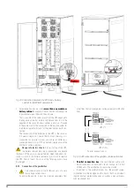
The increase in efficiency (of b2%~3%) is due to the
fact that while the bypass line is connected to the output, the
inverter is stopped, therefore the conduction and switching
losses of this converter are avoided.
Even when in bypass, the rectifier will remain in operation, with
the aim of the DC bus being within the operating ranges of the
inverter, allowing a quick intervention of the latter. In turn, the
charger will carry out periodic start-stop cycles for greater effi-
ciency of the system averaged over time, always monitoring the
possible self-discharge of the batteries and recharging them
when necessary.
MANUAL BYPASS
AC OUTPUT
BYPASS STATIC
SWITCH
INVERTER
DC-LINK
BATTERY
CHARGER
BATTERY PACK
AC INPUT
BYPASS
LINE
RECTIFIER-BOOSTER
Fig. 19.
UPS power flow in ECO mode.
4.5.6. Frequency converter mode
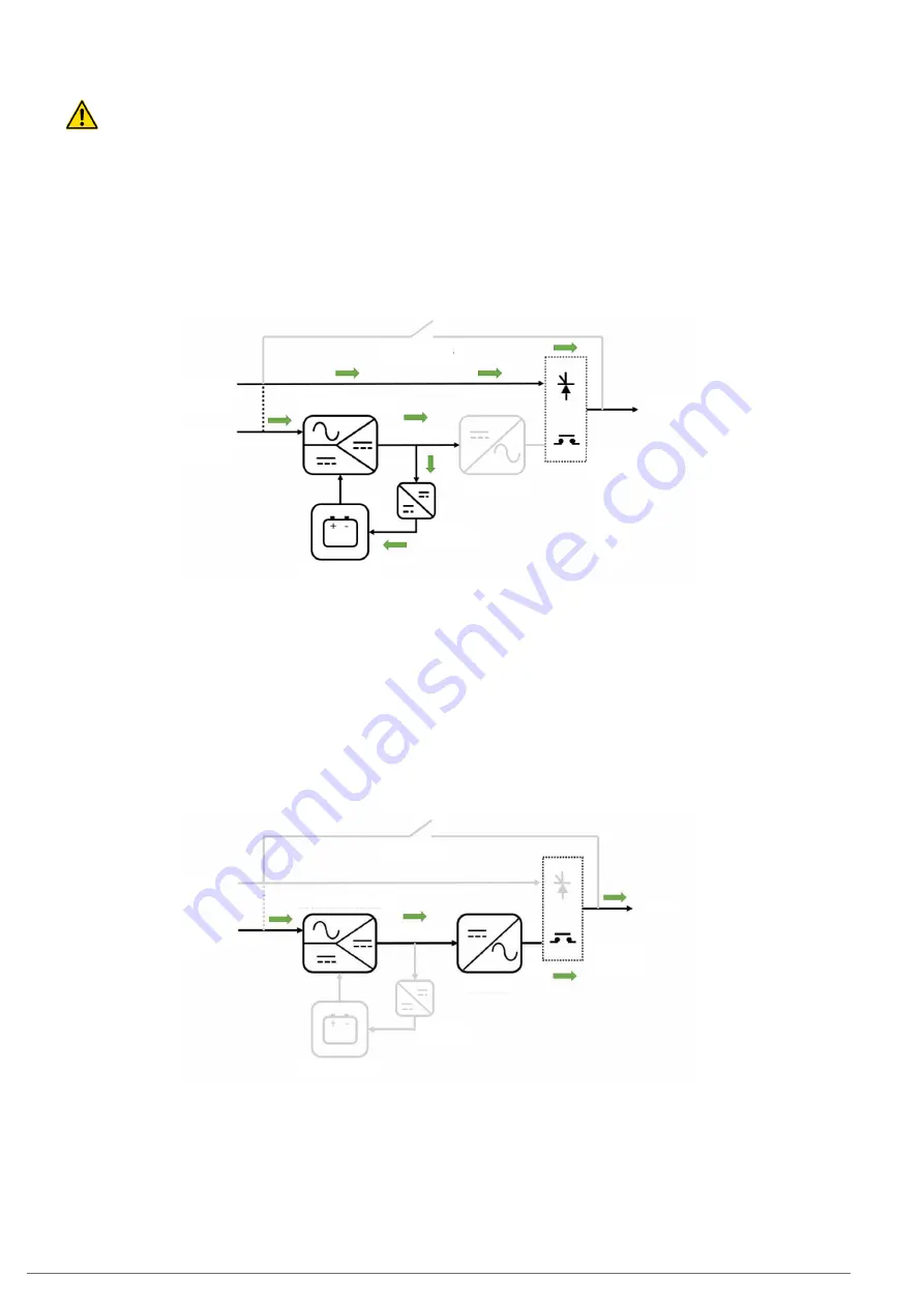
When operating in this mode, activated by configuration, the
unit supplies a fixed output frequency of 50 or 60 Hz, which may
be different to the input frequency. It consists of an operating
mode derived from normal mode, as double conversion is per-
formed, AC/DC rectifier and DC/AC inverter running.
When operating in this mode, the UPS static bypass is disabled,
and may not even be physically present in the unit construction
(if a frequency converter has been specifically ordered from the
factory). The manual bypass switch (if present) should also not
be actuated due to the possible impact on the loads connected
at the output.
The presence of batteries (and charger) is optional for this type
of unit.
MANUAL BYPASS
AC OUTPUT
BYPASS STATIC
SWITCH
INVERTER
DC-LINK
BATTERY
CHARGER
BATTERY PACK
AC INPUT
BYPASS
LINE
RECTIFIER-BOOSTER
Fig. 20.
UPS power flow in frequency converter mode.
4.6. OPERATION AND CONTROL DEVICES
The operation and control devices allow the UPS user/operator
to carry out the following actions, among others:
•
Unit start-up.
•
Special operations (such as switching to bypass mode).
•
Maintenance and repair interventions (maintenance bypass
mode).
SLC CUBE4
- UNINTERRUPTIBLE POWER SUPPLY SYSTEM
-
USER MANUAL
Содержание SLC CUBE 4
Страница 1: ...30 80 kVA USER MANUAL UNINTERRUPTIBLE POWER SUPPLY...
Страница 74: ...74 SALICRU...
Страница 75: ...75 SLC CUBE4 UNINTERRUPTIBLE POWER SUPPLY SYSTEM USER MANUAL...
Страница 76: ...76 SALICRU...
Страница 77: ...77 SLC CUBE4 UNINTERRUPTIBLE POWER SUPPLY SYSTEM USER MANUAL...


