

Remote control console
MB-GATEWAY
Quick Start Guide
P0114_AZ_0003
If connection fails (you have forgotten the password, IP address, etc.),
you can always restore to factory settings:
1.
Switch off the power source;
2.
Open the upper cover;
3.
While holding the button pressed, switch on the power source;
4.
Wait until the LED indications of the RJ45 connection begin flash
-
ing;
5.
The factory settings are restored as soon as the press-button is
released.
RESTORING TO FACTORY SETTINGS
Software upgrading requires a microSD card
SOFTWARE UPGRADING
1.
Downloading (http://salda.lt/lt/products/category/products/) up-
grade
FIRMWARE.BIN
and writing it to the microSD root catalogue.
2.
If writing through the FTP client, the power source should not be
switched off.
3.
If writing when the microSD card is removed from the module, the
power supply of the module must be switched off when inserting the
card.
4.
Insert the card and connect the power supply.
5.
If the file is proper, the module begins the upgrading procedure. The
RJ45 LED lamps flash alternately around every 1 s. The power source
must not be switched off during this process.
6.
After around 5 minutes, the module completes upgrading and
switches to the normal status.
7.
After upgrading,
FIRMWARE.BIN
is erased automatically.
RJ45 connection LED indications
• Both LED indications flash slowly and evenly – the MB-GATEWAY
has no software installed.
• The LED indications flash slowly and alternately – the software
upgrading is in progress.
• LED indications do not light – no power source and/or connection
with the Ethernet network.
Should any problems arise in the course of upgrading, please address
the local distributor.
This module also has an FTP server, so the content of the microSD
memory card can be accessed and edited without removing the card.
The login data of the FTP server are the same as those of the pro-
tected WEB pages. Make sure to indicated Passive Mode in the FTP
client programme.
FTP SERVER
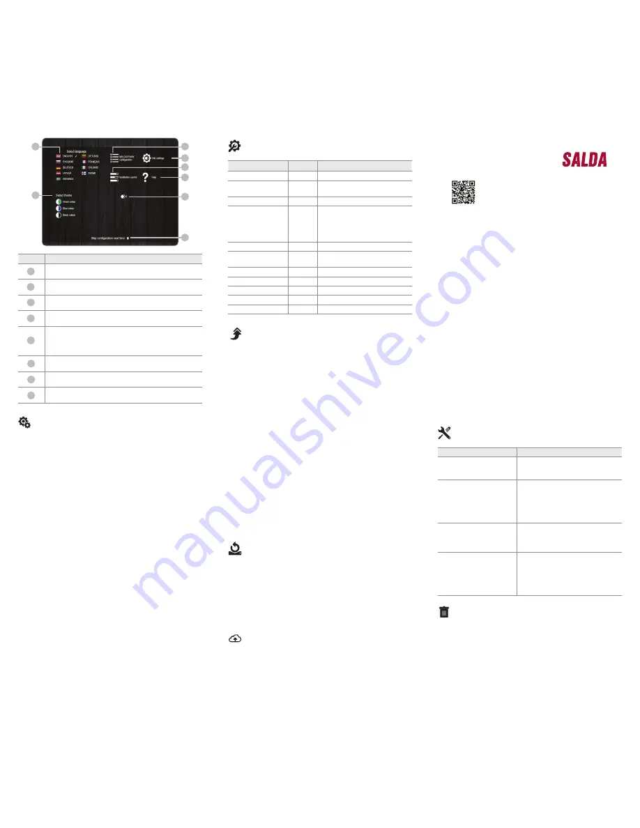
B2
B3
B5
B4
B6
B7
B8
B1
Number Function
Selecting the user environment language
Selecting the desired theme colour
Opening the MB-GATEWAY settings window
Opening the device settings window
Opening the automatics control window If the parameters of
RS485 communications line are set improperly or the device is
connected improperly, a message of failed search of the con-
trol panel is displayed upon pressing B4
Opening the help PDF window
The selected ventilation device is displayed
The displaying of this window at the time of the opening of the
page is activated/deactivated
B1
B2
B3
B4
B5
B6
B7
B8
TECHNICAL SPECIFICATIONS
Parameter
Units
Value
Anchoring
Surface, DIN rail
Voltage
[AC/DC]
12 V - 25 V (2 W) (included in the
supply with an AC/DC adapter)
Communications line
Ethernet RJ45, ModBus RS485
Cable length
[m]
UTP cable (1 m)
RS485 communications cable with
RJ10/RJ45 plugs (2 m)
RS485 communications cable with
RJ10/RJ10 plugs (2 m)
Power source
[mm]/[m]
73 x 40 x 38 mm/Cable – 1 m
Dimensions
(W x H x D)
[mm]
90 x 36 x 58
Package dimensions
[mm]
140 x 110 x 86
Package weight
[g]
340g ±10g
Protection class
IP-20
Ambient temperature
[°C]
-20 +70
Relative humidity
[%]
30-85 (without condensation)
SERVICE MODE
MB-GATEWAY service mode is triggered by holding down user button
for 2 seconds, while power is on. Service mode is indicated by slow
(constant period) flashing of orange RJ45 LED. MB-GATEWAY IP ad
-
dress in service mode is 192.168.0.51
Deactivation of DHCP / setting of TCP/IP static parameters
1. In the computer, to which you will connect the device, you should
set the static parameters of the TCP/IP panel. These settings de-
pend on the OS (see OS documents):
• the IP address should be in a range 192.168.0.1 – 192.168.0.254
(except 192.168.0.51), for example, 192.168.0.11;
• subnet mask ‒ 255.255.255.0.
2. Connect MB-GATEWAY to the configured computer with a UTP
(RJ45) cable (included in the supply). If it fails to operate (the com-
puter fails to support Auto MDI-X), the computer and MB-GATEWAY
should be connected to the network switch.
3. Connect the power supply unit (included in the supply) and hold
down user button for 2 seconds until MB-GATEWAY switches into
the service mode. Test the network connection using PING from
Command Prompt: ping 192.168.0.51
4. In the address window of the internet browser (Google Chrome
is recommended), enter
192.168.0.51
(MB-GATEWAY IP address
in service mode).
5. In the Web page that appears, select B3 ‒ MB-GATEWAY setting
window. Switch off DHCP support. Set TCP/IP static parameters.
If it is planned to interconnect several MB-GATEWAY in the local
network, they must be assigned unique IP addresses. After restart,
MB-GATEWAY will be available in the network by the new IP ad
-
dress you have assigned to it.
POSSIBLE ERRORS AND THEIR SOLUTION
Problem
Solution
Time indications are not
saved after restarting the
equipment
Check whether the spare power battery
is inserted
Failed connection to the ven-
tilation unit
(Connection lost
or Control board not found
message)
• Check the connection settings;
• Check the power source;
• Check the communication cables (Eth-
ernet, PRV/MCB);
• Check the communication configuration
switches on the MCB or miniMCB panel;
The WEB environment is not
displayed after entering the
IP address in the browser
window
Check whether the microSD card is
inserted properly
The MB-Gateway module
does not operate / the indica-
tors on the RJ45 connection
do not flash after connecting
a power source and commu-
nication cables
Address the supplier
DISPOSAL
• In managing the waste equipment, comply with effective rules.
• In order to reduce impact on the environment and public health, re-
move the equipment to an electronics waste site or container.
• For detailed information concerning processing, address the seller
supplier.
Waste electrical and electronic equipment


