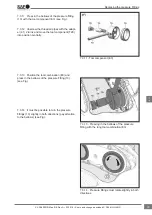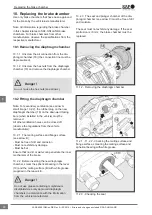
10.2.4 Locate the diaphragm chamber (see Fig.).
Note: To prevent the diaphragm chamber from
tilting whilst being tightened, the new self-locking
hex nuts of the diaphragm chamber must be hand
tightened symmetrically with a suitable tool.
10.2.5 Tighten both self-locking hex nuts in
accordance with the information from the brake
chamber manufacturer.
10.2.6 Tighten the brake hose to the diaphragm
chamber, ensuring that the hose does not twist and
is routed such that chafing cannot occur!
10.2.7 Check that the air connection is leak tight.
Perform a function and effectiveness check of
the BBA!
Danger !
10.3 Removing the combined chamber
Before loosening the combined chamber, secure
the vehicle to prevent it from rolling away.
Danger !
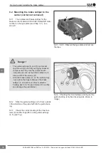
10.3.1 Release the parking brake.
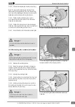
10.3.2 Move the spring mechanism emergency
release spindle (arrow D) to the release position
(observe the regulations from the vehicle manufac-
turer) (see Fig.).
10.3.3 Actuate the parking brake.
10.3.4 Unscrew the air connections from the com-
bined chamber (18) (the connection line must be
depressurised).
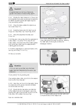
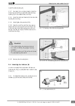
10.3.5 Unscrew both self-locking hex nuts from
the combined chamber (18) and remove the com-
bined chamber (18) (see Fig.).
Unscrew the hex nuts from the combined
chamber (18) and do not re-use.
Danger !
11.2.4 - Locating the diaphragm chamber
11.3.2 - Moving the spring mechanism emergency
release spindle to the release position
11.3.5 - Removing the SAF-HOLLAND combined
chamber
Replacing the brake chamber
47
en
XL-SA40001RM-en-DE Rev A • 02.2016 • Errors and changes excluded © SAF-HOLLAND

