7.3
Mounting the pressure fittings with
bellows (13)
The pressure fittings are supplied with special long-
term lubrication and a protective cap.
Before mounting, the protective cap must be
removed and properly disposed of. The grease
must not be smeared or removed.
Grease contamination onto the bellows or other
components must be avoided. In addition,
additional greasing of the pressure fittings with
other lubricants is not permitted.
With the brake calliper installed:
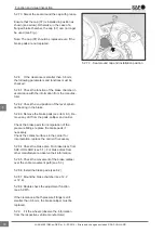
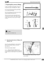
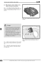
7.3.1
The pressure fittings (13) must be mounted
with the tool combination (E1) shown (see Fig.).
7.3.2 Fully turn back the threaded pipes (16) with
the adapter (61) (see Chap. 6.1.4).
Note: The seal for the bellows in the brake calliper
must be clean and free of grease.
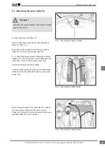
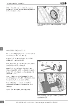
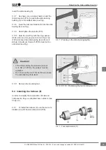
7.3.3 Fit the new slide bearing bushing (161) to
the threaded pipes (16) and fit the pressure fitting
with bellows (13) to the base of the threaded pipe
(16).
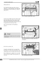
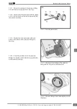
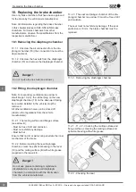
7.3.4 Position the tool combination (E1) and
mount the pressure fitting (13) to the threaded pipe
by unscrewing the tool component (T03).
Note: The tool component (T55) is not required for
this mounting step.
7.3.5 Turn the tool combination (E1).
Note: Before performing the next step, insert the
tool component (T55) into the tool component
(T28).
7.3.6 Unscrew the threaded pipes with the adapt-
er (61) 2 turns and move the tool component (T28)
into position centrally as shown.
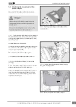
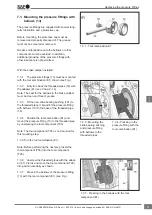
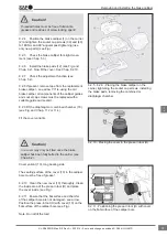
7.3.7
Press in the bellows of the pressure fitting
(13) with the tool component (E1) (see Fig.).
7.3.1 - Tool combination E1
7.3.7 - Pressing in the bellows with the tool
component (E1)
7.3.3 - Mounting the
slide bearing bushing
and pressure fitting
with bellows to the
threaded pipes
7.3.4 - Pressing in the
pressure fitting with the
tool combination (E1)
Replacing the pressure fittings
31
en
XL-SA40001RM-en-DE Rev A • 02.2016 • Errors and changes excluded © SAF-HOLLAND


