


IP
PC
ENCODER
SR
T2384
SMC_I/O
Telecamera
004AZ011B
FEATURES
2
2-17
2.4.2
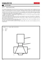
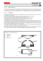
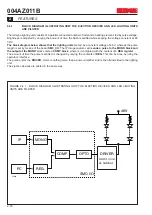
BLOCK DIAGRAM ILLUSTRATING THE IMAGE SHOOTING SENSORS AND ENCODER INTERFACE
The position of the product to be inspected can be tracked by the system in different ways depending on the
configuration and whether or not an encoder is used.
Presence sensor
SR
informs the system a product has passed by. The signal is transmitted to the
SMC I/O
board,
which filters and delays it as required. The
SMC I/O
board therefore tracks the product using the
ENCODER
or
internal timer. When required, a signal is sent to the
IP
card to acquire the image. When deemed necessary a signal
is sent to the solenoid valve to eject the product, if judged defective.
The position of the camera/s and ejector/s (in relation to the sensor) can be changed. They can be set by the user
with the program interface.
The encoder should be used when the products are carried on a conveyor belt. In some cases, an internal timer can
be used if the belt speed is perfectly steady.
When the CVS is installed on a synchronous machine and the products are equally spaced apart, the CVS is timed
with the sensor. In this case the encoder is not used.
Thanks to the user interface, the delay time for the image shooting sensor and the number of encoder steps between
the shooting and ejection operations can be modified as required.
FIGURE 2.4.2 - BLOCK DIAGRAM ILLUSTRATING THE IMAGE SHOOTING SENSORS AND ENCODER
INTERFACE
Camera
Содержание CVS Series
Страница 2: ......
Страница 4: ...004AZ011B...
Страница 8: ...004AZ011B TABLE OF CONTENTS Page 0 8...
Страница 16: ...004AZ011B 1 GENERAL INFORMATION 1 8...
Страница 37: ...T6912 SAFETY EQUIPMENT AND PRECAUTIONS 3 3 3 004AZ011B FIGURE 3 1 2 LOCKOUT TAGOUT QS1...
Страница 46: ...3 SAFETY EQUIPMENT AND PRECAUTIONS 3 12 004AZ011B...
Страница 52: ...UPS T6785 4 INSTALLATION 4 6 004AZ011B FIGURE 4 3 1 1 CONNECTING THE ELECTRIC CABLES 1 3 2 4 CAMERA LINK...
Страница 62: ...7 ADJUSTMENTS 7 4 004AZ011B...
Страница 66: ...8 MAINTENANCE 8 4 004AZ011B...


