


T2379
3
1
2
004AZ011B
FEATURES
2
2-7
2.1.1.5
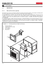
Additional electrical cabinet
The additional cabinet is placed near the operator interface cabinet. It houses the components employed to
communicate with the lighting units, ejectors and image capture signal.
The following components are housed in the cabinet:
- A card set up to control 6 lighting units, 2 ejectors, 5 inputs (sensors, encoders) and a status indicator tower.
- Terminal block (XT1)
1
that joins the card to the accessories.
- Terminal block (XT2)
2
that feeds the card.
- 37-pin D connector (XJ1)
3
that joins the secondary electrical cabinet to the main one.
Refer to the wiring diagrams for the location of the components.
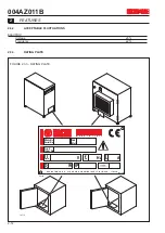
FIGURE 2.1.1.5 - ADDITIONAL ELECTRICAL CABINET
1
Terminal block (XT1)
2
Terminal block (XT2)
3
37-pin D connector (XJ1)
Содержание CVS Series
Страница 2: ......
Страница 4: ...004AZ011B...
Страница 8: ...004AZ011B TABLE OF CONTENTS Page 0 8...
Страница 16: ...004AZ011B 1 GENERAL INFORMATION 1 8...
Страница 37: ...T6912 SAFETY EQUIPMENT AND PRECAUTIONS 3 3 3 004AZ011B FIGURE 3 1 2 LOCKOUT TAGOUT QS1...
Страница 46: ...3 SAFETY EQUIPMENT AND PRECAUTIONS 3 12 004AZ011B...
Страница 52: ...UPS T6785 4 INSTALLATION 4 6 004AZ011B FIGURE 4 3 1 1 CONNECTING THE ELECTRIC CABLES 1 3 2 4 CAMERA LINK...
Страница 62: ...7 ADJUSTMENTS 7 4 004AZ011B...
Страница 66: ...8 MAINTENANCE 8 4 004AZ011B...


