


Instruction manual V 2.3
37
PWM 230 - PWM 400 - PWM 400/7.5
Instruction manual
-
Maximum frequency limiting as temperature increases over a potentially dangerous value
The second type of protection is used on:
- power
devices
- supply
capacitor
- printed
circuit
It acts when a potentially dangerous temperature is reached, by gradual decrease of the maximum
frequency of rotation FS. The purpose is that of reducing power dissipation thus protecting the PWM against
overheating. Once the alarm cause disappears, the protection is automatically disabled and normal
operation conditions are restored. Intervention of one or more of these protections can only decrease the
frequency FS by no more than 20%.
The three protection systems don't cause a block and don't produce any error message, but keep track of
their intervention by insertion of an alarm in the fault history (see sec. 5.2.2.7).
Note:
during intervention of such protections a FR frequency of rotation smaller than the expected one
could be displayed.
If the temperature of the final output stage or of the printed circuit is not successfully limited by the
mentioned protections, an overtemperature blockage will occur.
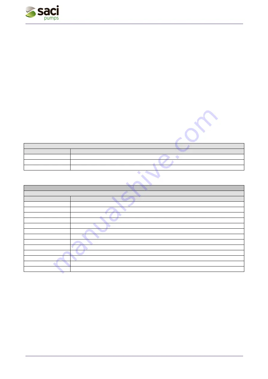
Warning on the fault history queue
Display indications
Description
Lt
Overtemperature on the power devices alarm (tE > 85°C)
LC
Overtemperature on capacitor alarm
Lb
Overtemperature on printed circuit alarm (bt > 100°C)
Table 12: Warning on the fault history queue
Error conditions
Error and status conditions
Display indications
Description
bL
Blockage due to lack of water
bP
Blockage due to disconnected pressure sensor
LP
Blockage due to low supply voltage
HP
Blockage due to high rectified voltage
Ot
Blockage due to overheating of the power output stages (tE > 100°C)
Ob
Blockage due to overheating of the printed circuit (bt > 120°C)
OC
Blockage due to overcurrent in the electro pump motor
OF
Blockage due to overcurrent in the output stages
SC
Blockage due to direct short circuit between the phases of output terminals
EC
Blockage due to incorrect setting of the rated current (rC) or rated frequency (Fn)
E0...E7
Blockage due to internal error 0...7
F1
Status / Blockage due to input 1 status
F3
Status / Blockage due to input 3 status
Table 13: Error conditions
“bL” Blockage due to lack of water
In no flow conditions the system turns off the pump. If the pressure is lower than the set point one, the
display shows a lack of water message.
If you wrongly set a pressure set point higher than the pressure that the electro pump is able to supply, the
system will sign “lock due to lack of water” (bL) even if there is no lack of water. So you should lower the set-
point pressure at a reasonable value that usually does not exceed 2/3 of the of the installed electro pump’s
head.
Note: The PWM system operates at constant pressure. This regulation is appreciable if the hydraulic
system downstream from the system is properly sized. Systems with too narrow pipes lead to a