Instruction manual V 2.3
19
PWM 230 - PWM 400 - PWM 400/7.5
Instruction manual
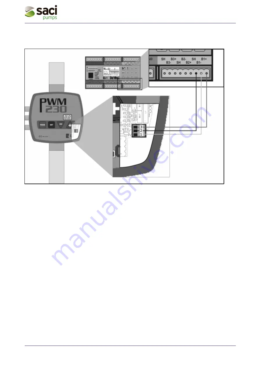
Figure 14: Wiring diagram for connection of PWM to the “Da Vinci” controller board.
Note:
For PWM systems wired and configured to work with “Da Vinci” controller board operation of input 2
is disabled (see sec. 5.1.3.9.2), a new menu called “AS” is activated (see sec. 5.2.1.4) and the “rP”
parameter becomes unavailable (see sec. 5.1.2.5).

