Instruction manual V 2.3
5
PWM 230 - PWM 400 - PWM 400/7.5
Instruction manual
TABLES INDEX
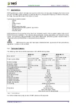
Table 1: Technical features ............................................................................................................................... 8
Table 2: PWM 230 power supply requirements .............................................................................................. 10
Table 3: Minimum section as a function of power cord’s length for PWM 230................................................ 11
Table 4: PWM 400 power supply requirements .............................................................................................. 12
Table 5: Minimum section as a function of power cord’s length for PWM 400................................................ 13
Table 6: Optocoupled input contacts ratings ................................................................................................... 16
Table 7: Pinout of cable used for communication between PWM and "Da Vinci" controller board................. 18
Table 8: Meaning of the messages shown on the display............................................................................... 22
Table 9: Problems solving ............................................................................................................................... 26
Table 10: inputs configuration ......................................................................................................................... 34
Table 11: Assigning output function ................................................................................................................ 35
Table 12: Warning on the fault history queue.................................................................................................. 37
Table 13: Error conditions ............................................................................................................................... 37
Table 14: Automatic reset of error conditions.................................................................................................. 39
Table 15: Keys usage in manual mode ........................................................................................................... 40
Table 16: Factory settings ............................................................................................................................... 43
Table 17: Energy saving.................................................................................................................................. 44
FIGURES INDEX
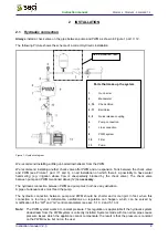
Figure 1: Hydraulic diagram .............................................................................................................................. 9
Figure 2: Power supply terminal ...................................................................................................................... 11
Figure 3: Wrong connection ............................................................................................................................ 11
Figure 4: Right connection............................................................................................................................... 11
Figure 5: Three-phase electro pump output terminal ...................................................................................... 12
Figure 6: Power supply line input terminals..................................................................................................... 13
Figure 7: Connection to be made on a motor managed by PWM 400 ............................................................ 14
Figure 8: Three-phase electro pump output terminal ...................................................................................... 14
Figure 9: User output terminal ......................................................................................................................... 15
Figure 10: Example application of user outputs .............................................................................................. 15
Figure 11: User input terminal ......................................................................................................................... 16
Figure 12: User inputs usage example............................................................................................................ 17
Figure 13: Wiring diagram for two PWM in exchange ..................................................................................... 18
Figure 14: Wiring diagram for connection of PWM to the “Da Vinci” controller board. ................................... 19
Figure 15: PWM’s Keypad and Display. .......................................................................................................... 20
Figure 16: PWM’s pressure loss...................................................................................................................... 44


