SOUTHERN AVIONICS COMPANY
Model SA100 Dual
2-32
Theory of Operation, Radiobeacon
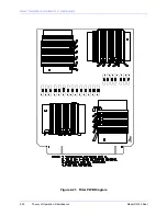
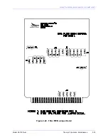
2.3.9 Filter
SLP29700 is the Standard Band Filter
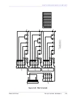
The square wave output from the Switching Power Amplifier is filtered on the 5 band FILTER
PCB. The filter is a modified symmetrical 7 element 50 ohm Butterworth filter. Standard
frequency bands, chosen with jumpers, are 190-220 KHz, 220-280 KHz, 280-360 KHz, 360-440
KHz, and 440-535 KHz.
SLP29720 is the extended band filter. It has jumpers for one frequency band of 535 - 625 KHz.
SLP29740 is the “M” Band Filter. It has jumper settings for the following bands: 500-650 KHz,
650-800 KHz, 800-950 KHz, 950-1000 KHz and 1100-1250 KHz.
SLP29730 is the “H” Band Filter. It’s jumpers are set for one frequency band of 1500-1800KHz.
Jumper tables exist for each of the PCB’s schematics.
Содержание SA100
Страница 20: ...SOUTHERN AVIONICS COMPANY Model SA100 Dual x Contents...
Страница 22: ...SOUTHERN AVIONICS COMPANY Model SA100 Dual 1 2 Introduction This page intentionally left blank...
Страница 24: ...SOUTHERN AVIONICS COMPANY Model SA100 Dual 1 4 Introduction Figure 1 1 Transmitter Enclosure Dimensions...
Страница 25: ...SOUTHERN AVIONICS COMPANY Model SA100 Dual 1 5 Introduction Figure 1 2 Transmitter Portrait...
Страница 26: ...SOUTHERN AVIONICS COMPANY Model SA100 Dual 1 6 Introduction This page intentionally left blank...
Страница 28: ...SOUTHERN AVIONICS COMPANY Model SA100 Dual 1 8 Introduction This page intentionally left blank...
Страница 36: ...SOUTHERN AVIONICS COMPANY Model SA100 Dual 2 6 Theory of Operation Radiobeacon Figure 2 2 Block Diagram...
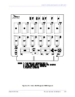
Страница 39: ...SOUTHERN AVIONICS COMPANY Model SA100 Dual 2 9 Theory of Operation Radiobeacon Figure 2 4 KWOSYN PWB Diagram...
Страница 43: ...SOUTHERN AVIONICS COMPANY Model SA100 Dual 2 13 Theory of Operation Radiobeacon Figure 2 6 Tone Key PWB Diagram...
Страница 45: ...SOUTHERN AVIONICS COMPANY Model SA100 Dual 2 15 Theory of Operation Radiobeacon Figure 2 7 Audio PWB Schematic...
Страница 46: ...SOUTHERN AVIONICS COMPANY Model SA100 Dual 2 16 Theory of Operation Radiobeacon Figure 2 8 Audio PWB Diagram...
Страница 48: ...SOUTHERN AVIONICS COMPANY Model SA100 Dual 2 18 Theory of Operation Radiobeacon Figure 2 9 ACTRL Schematic...
Страница 49: ...SOUTHERN AVIONICS COMPANY Model SA100 Dual 2 19 Theory of Operation Radiobeacon Figure 2 10 ACTRL Diagram...
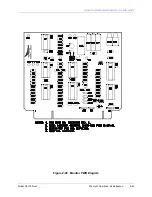
Страница 53: ...SOUTHERN AVIONICS COMPANY Model SA100 Dual 2 23 Theory of Operation Radiobeacon Figure 2 13 CRS Sample Program...
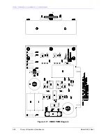
Страница 58: ...SOUTHERN AVIONICS COMPANY Model SA100 Dual 2 28 Theory of Operation Radiobeacon D Figure 2 17 DMOD PWB Diagram...
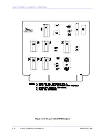
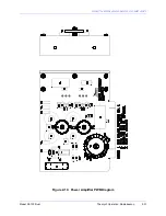
Страница 64: ...SOUTHERN AVIONICS COMPANY Model SA100 Dual 2 34 Theory of Operation Radiobeacon Figure 2 21 Filter PWB Diagram...
Страница 68: ...SOUTHERN AVIONICS COMPANY Model SA100 Dual 2 38 Theory of Operation Radiobeacon Figure 2 24 HWRF PWB Diagram...
Страница 70: ...SOUTHERN AVIONICS COMPANY Model SA100 Dual 2 40 Theory of Operation Radiobeacon Figure 2 26 AMTR Diagram...
Страница 73: ...SOUTHERN AVIONICS COMPANY Model SA100 Dual 2 43 Theory of Operation Radiobeacon Figure 2 29 Monitor PWB Diagram...
Страница 75: ...SOUTHERN AVIONICS COMPANY Model SA100 Dual 2 45 Theory of Operation Radiobeacon Figure 2 31 SA LED PWB Diagram...
Страница 82: ...SOUTHERN AVIONICS COMPANY Model SA100 Dual 2 52 Theory of Operation Radiobeacon Figure 2 37 DCHOKE PWB Diagram...
Страница 105: ...SOUTHERN AVIONICS COMPANY Model SA100 Dual 2 75 Theory of Operation Radiobeacon Figure 2 56 DC Auto Disconnect Diagram...
Страница 110: ...SOUTHERN AVIONICS COMPANY Model SA100 Dual 2 80 Theory of Operation Radiobeacon Figure 2 59 Modem PWB Schematic...
Страница 111: ...SOUTHERN AVIONICS COMPANY Model SA100 Dual 2 81 Theory of Operation Radiobeacon Figure 2 60 Modem PWB Assembly...
Страница 116: ...SOUTHERN AVIONICS COMPANY Model SA100 Dual 2 86 Theory of Operation Radiobeacon This page intentionally left blank...
Страница 119: ...SOUTHERN AVIONICS COMPANY Model SA100 Dual 3 3 Antennas Figure 3 1 Antenna Reactance...
Страница 120: ...SOUTHERN AVIONICS COMPANY Model SA100 Dual 3 4 Antennas This page intentionally left blank...
Страница 122: ...SOUTHERN AVIONICS COMPANY Model SA100 Dual 4 2 Installation and Operation Figure 4 1 Interconnecting Wire Diagram...
Страница 123: ...SOUTHERN AVIONICS COMPANY Model SA100 Dual 4 3 Installation and Operation Figure 4 2 Input Output Terminal Blocks...
Страница 124: ...SOUTHERN AVIONICS COMPANY Model SA100 Dual 4 4 Installation and Operation This page intentionally left blank...
Страница 159: ...SOUTHERN AVIONICS COMPANY Model SA100 Dual 5 7 Maintenance Figure 5 1 Troubleshooting Flow Chart...
Страница 160: ...SOUTHERN AVIONICS COMPANY Model SA100 Dual 5 8 Maintenance This page intentionally left blank...
Страница 162: ...SOUTHERN AVIONICS COMPANY Model SA100 Dual 6 2 Parts List This page intentionally left blank...
Страница 164: ...SOUTHERN AVIONICS COMPANY Model SA100 Dual 6 4 Parts List This page intentionally left blank...
Страница 218: ...SOUTHERN AVIONICS COMPANY Model SA100 Dual 6 58 Parts List This page intentionally left blank...
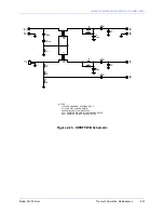
Страница 220: ...SOUTHERN AVIONICS COMPANY Model SA100 Dual 7 2 Modifications Figure 7 1 EMI Filter Module Schematic...
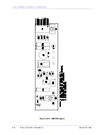
Страница 221: ...SOUTHERN AVIONICS COMPANY Model SA100 Dual 7 3 Modifications Figure 7 2 EMI Filter Module Diagram...
Страница 224: ...SOUTHERN AVIONICS COMPANY Model SA100 Dual 7 6 Modifications This page intentionally left blank...


