SOUTHERN AVIONICS COMPANY
Model SA100 Dual
4-29
Installation and Operation
4.8 Modulation Adjustment
The transmitter can be operated in several different modulation modes. With normal NDB
operation without voice, the identifier tone amplitude modulates the carrier according to the
assigned identifier code at a high modulation level. The initial set up procedure assumed this
mode of operation. The transmitter can also be used with voice modulation alone, or with
simultaneous voice modulation and code tone modulation. The selection of these options is
made with jumpers on the Tone Key PWB.
1. For standard NDB operation with identifier code tone modulation only, no jumpers are used,
and no Audio PWB is used. If this mode is selected, complete the Code Tone Modulation
Adjustment section and proceed to the VSWR Shutdown section.
2. For voice modulation only, the MODE switch is left in CARR, an Audio PWB is used, and the
placement of jumpers on the Tone Key PWB is irrelevant. If this mode is selected, complete
the Voice Modulation Adjustment section and proceed to the VSWR Shutdown section.
3. For simultaneous voice and code tone modulation, an Audio PWB is used, and a jumper is
placed on the Tone Key PWB connecting pin 13 of U2 to pin 22 of the board (A to B). This
selection allows the code tone to operate at full modulation percentage except when a voice
signal is present. When a voice signal is present the squelch control decreases the code
tone modulation to 20% so that the identifier can be heard in the background of the voice
signal. If the automatic increase of code tone modulation percentage in the absence of voice
is not desired, a jumper is placed from pin 13 of U2 on the Tone Key PWB to ground (A to C).
This causes the code tone modulation percentage to remain at 20% irrespective of the voice
signal. The modulation percentage of the code tone is controlled by R11 on the Tone Key
PWB. A different value resistor can be used or the resistor can be completely removed if a
higher or lower modulation percentage is desired during voice transmission. Removal of the
resistor silences the code tone. Install jumpers, change resistor value if desired, and
complete the Code Tone Modulation Adjustment and the Voice Modulation Adjustment
Sections.
Содержание SA100
Страница 20: ...SOUTHERN AVIONICS COMPANY Model SA100 Dual x Contents...
Страница 22: ...SOUTHERN AVIONICS COMPANY Model SA100 Dual 1 2 Introduction This page intentionally left blank...
Страница 24: ...SOUTHERN AVIONICS COMPANY Model SA100 Dual 1 4 Introduction Figure 1 1 Transmitter Enclosure Dimensions...
Страница 25: ...SOUTHERN AVIONICS COMPANY Model SA100 Dual 1 5 Introduction Figure 1 2 Transmitter Portrait...
Страница 26: ...SOUTHERN AVIONICS COMPANY Model SA100 Dual 1 6 Introduction This page intentionally left blank...
Страница 28: ...SOUTHERN AVIONICS COMPANY Model SA100 Dual 1 8 Introduction This page intentionally left blank...
Страница 36: ...SOUTHERN AVIONICS COMPANY Model SA100 Dual 2 6 Theory of Operation Radiobeacon Figure 2 2 Block Diagram...
Страница 39: ...SOUTHERN AVIONICS COMPANY Model SA100 Dual 2 9 Theory of Operation Radiobeacon Figure 2 4 KWOSYN PWB Diagram...
Страница 43: ...SOUTHERN AVIONICS COMPANY Model SA100 Dual 2 13 Theory of Operation Radiobeacon Figure 2 6 Tone Key PWB Diagram...
Страница 45: ...SOUTHERN AVIONICS COMPANY Model SA100 Dual 2 15 Theory of Operation Radiobeacon Figure 2 7 Audio PWB Schematic...
Страница 46: ...SOUTHERN AVIONICS COMPANY Model SA100 Dual 2 16 Theory of Operation Radiobeacon Figure 2 8 Audio PWB Diagram...
Страница 48: ...SOUTHERN AVIONICS COMPANY Model SA100 Dual 2 18 Theory of Operation Radiobeacon Figure 2 9 ACTRL Schematic...
Страница 49: ...SOUTHERN AVIONICS COMPANY Model SA100 Dual 2 19 Theory of Operation Radiobeacon Figure 2 10 ACTRL Diagram...
Страница 53: ...SOUTHERN AVIONICS COMPANY Model SA100 Dual 2 23 Theory of Operation Radiobeacon Figure 2 13 CRS Sample Program...
Страница 58: ...SOUTHERN AVIONICS COMPANY Model SA100 Dual 2 28 Theory of Operation Radiobeacon D Figure 2 17 DMOD PWB Diagram...
Страница 64: ...SOUTHERN AVIONICS COMPANY Model SA100 Dual 2 34 Theory of Operation Radiobeacon Figure 2 21 Filter PWB Diagram...
Страница 68: ...SOUTHERN AVIONICS COMPANY Model SA100 Dual 2 38 Theory of Operation Radiobeacon Figure 2 24 HWRF PWB Diagram...
Страница 70: ...SOUTHERN AVIONICS COMPANY Model SA100 Dual 2 40 Theory of Operation Radiobeacon Figure 2 26 AMTR Diagram...
Страница 73: ...SOUTHERN AVIONICS COMPANY Model SA100 Dual 2 43 Theory of Operation Radiobeacon Figure 2 29 Monitor PWB Diagram...
Страница 75: ...SOUTHERN AVIONICS COMPANY Model SA100 Dual 2 45 Theory of Operation Radiobeacon Figure 2 31 SA LED PWB Diagram...
Страница 82: ...SOUTHERN AVIONICS COMPANY Model SA100 Dual 2 52 Theory of Operation Radiobeacon Figure 2 37 DCHOKE PWB Diagram...
Страница 105: ...SOUTHERN AVIONICS COMPANY Model SA100 Dual 2 75 Theory of Operation Radiobeacon Figure 2 56 DC Auto Disconnect Diagram...
Страница 110: ...SOUTHERN AVIONICS COMPANY Model SA100 Dual 2 80 Theory of Operation Radiobeacon Figure 2 59 Modem PWB Schematic...
Страница 111: ...SOUTHERN AVIONICS COMPANY Model SA100 Dual 2 81 Theory of Operation Radiobeacon Figure 2 60 Modem PWB Assembly...
Страница 116: ...SOUTHERN AVIONICS COMPANY Model SA100 Dual 2 86 Theory of Operation Radiobeacon This page intentionally left blank...
Страница 119: ...SOUTHERN AVIONICS COMPANY Model SA100 Dual 3 3 Antennas Figure 3 1 Antenna Reactance...
Страница 120: ...SOUTHERN AVIONICS COMPANY Model SA100 Dual 3 4 Antennas This page intentionally left blank...
Страница 122: ...SOUTHERN AVIONICS COMPANY Model SA100 Dual 4 2 Installation and Operation Figure 4 1 Interconnecting Wire Diagram...
Страница 123: ...SOUTHERN AVIONICS COMPANY Model SA100 Dual 4 3 Installation and Operation Figure 4 2 Input Output Terminal Blocks...
Страница 124: ...SOUTHERN AVIONICS COMPANY Model SA100 Dual 4 4 Installation and Operation This page intentionally left blank...
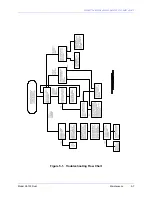
Страница 159: ...SOUTHERN AVIONICS COMPANY Model SA100 Dual 5 7 Maintenance Figure 5 1 Troubleshooting Flow Chart...
Страница 160: ...SOUTHERN AVIONICS COMPANY Model SA100 Dual 5 8 Maintenance This page intentionally left blank...
Страница 162: ...SOUTHERN AVIONICS COMPANY Model SA100 Dual 6 2 Parts List This page intentionally left blank...
Страница 164: ...SOUTHERN AVIONICS COMPANY Model SA100 Dual 6 4 Parts List This page intentionally left blank...
Страница 218: ...SOUTHERN AVIONICS COMPANY Model SA100 Dual 6 58 Parts List This page intentionally left blank...
Страница 220: ...SOUTHERN AVIONICS COMPANY Model SA100 Dual 7 2 Modifications Figure 7 1 EMI Filter Module Schematic...
Страница 221: ...SOUTHERN AVIONICS COMPANY Model SA100 Dual 7 3 Modifications Figure 7 2 EMI Filter Module Diagram...
Страница 224: ...SOUTHERN AVIONICS COMPANY Model SA100 Dual 7 6 Modifications This page intentionally left blank...

