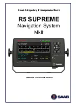
R5
SUPREME - Navigation System MkII
INSTALLATION
7000 118-383, B1
Page 15
5.2
Equipment Installation Environment
The table below lists the IEC 60945 equipment classification for the system.
Name
Part number
IEC 60945
installation category
R5 SUPREME CDU
7000 118-530
Protected
R5 GNSS Navigation Sensor
7000 118-770
Protected
R5 DGNSS Navigation Sensor
7000 118-771
Protected
MGA-3 GNSS Antenna
7000 000-554
Exposed
MGL-5 Combined GNSS / Beacon
Antenna
7000 000-555
Exposed
5.3
Installation Cables
The following cables are used to install the standard R5 SUPREME Navigation System.
R5 Power Cable
Marking:
7000 118-077
Application:
R5 CDU power port to R5 NAV Junction box or external power.
Type:
Unshielded 4 wire cable x 1.3 mm2
Length:
2 m
Diameter:
6 mm
Minimum bending radius: 10 times cable diameter
Connector:
ConXall Mini-Con-X 6382-4SG-311 (female) to open ends
Interconnection specification:
Pin
Cable Colour
1
Red
2
Black
3
Brown
4
Orange
Table 2
– R5 Power Cable interconnection
R5 Navigation Sensor GNSS Antenna Cable
Type:
See section 5.8.2
Length:
See section 5.8.2
Connector:
TNC (Male)
Minimum bending radius: 5 times cable diameter
Содержание R5 SUPREME MkII
Страница 1: ...OPERATION INSTALLATION MANUAL Saab AB publ TransponderTech R5 SUPREME Navigation System MkII...
Страница 2: ...This page is intentionally empty...
Страница 165: ...R5 SUPREME Navigation System MECHANICAL DRAWINGS 7000 118 383 P11A1 Page 165 20 2 CDU Panel Mount Cutout Hole dimensions...


