

7
I n p u t / L o w V o l t a g e S u p p l y L i n e
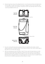
1.
Bring the low voltage supply power conduit to one of the two, lower right or left side input
power conduit knockout locations. On CLSFJB2 models, one or two conduits may be used for
the low voltage luminaire input power depending on power source locations and if separated
lighting controls are required. DO NOT use any of the bottom conduit connection locations for
input power – these are reserved for the fiber conduit (output) locations.
*Note:
The wiring of the 12VAC input and fiber cable/s are required to use separate conduits
and must not share an individual conduit. No conduit should contain both 12VAC input power
and fiber optic cables.
2. Using a hole saw, open the knockouts for the size of the conduit (¾” or 1”) being installed.
3. Attach an approved ‘rain-tight’ or ‘wet location’ hub to the conduit. After the hub is attach
to the conduit, attached the hub to the enclosure.
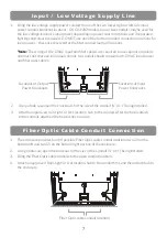
Locations of Input
Power Knockouts
Locations of Output
Power Knockouts
F i b e r O p t i c C a b l e C o n d u i t C o n n e c t i o n
1.
The enclosure provides four (4) possible Fiber Optic cable conduit locations, two (2) on the
bottom left and two (2) on the bottom right portion of the enclosure.
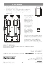
2. Using a hole saw, open the knockout for the size of the conduit (¾” or 1”) being installed.
3. Bring the Fiber Optic cable conduits to the open conduit locations.
4. Attach an approved ‘Rain-tight’ or ‘wet location’ hub to the conduit first, and then attach hub to
the enclosure.
Fiber Optic cable conduit locations