background image

Reverse With Confidence

 ™

1

G-SERIES Rear View Replacement Mirror Monitor with 

Auto-Dimming, Compass and Temperature

RVS-M628

Instruction Manual

RVS Systems, Inc. 

© 2016

Содержание G Series

Страница 1: ...ReverseWithConfidence 1 G SERIES Rear View Replacement Mirror Monitor with Auto Dimming Compass and Temperature RVS M628 Instruction Manual RVS Systems Inc 2016 ...

Страница 2: ... 03 Safety Information 04 06 Before Beginning Installation 07 Installation Guide 08 09 Adjustable Grid Line 10 Installation and Wire 11 13 Monitor Specifications 14 Troubleshooting 15 Warranty Disclaimer 16 17 TABLE OF CONTENTS ...

Страница 3: ...s intended to be installed as a supplement aid to your standard rear view mirror that already exists in your vehicle The Backup Camera System should not be used as a substitute for the standard rear view mirror or for any other mirror that exists in your vehicle In some jurisdictions it is unlawful for a person to drive a motorvehicleequippedwithaTVviewerorscreenlocatedforwardof the back of the dr...

Страница 4: ... mustuseit properly Use of this system is not a substitute for safe proper or legal driving Neverbackupwhilelookingatthe monitor alone You should always check behind and around the vehi cle when backing up in the same way as you would if the vehicle did not have the RearView Camera System Ifyoubackupwhilelooking only at the monitor you may cause damage or injury Always back up slowly The Rear View...

Страница 5: ...immediately Wherethepowercablemaytouch a metal case cover the cable with a friction tape A short circuit or disconnected wire may cause a fire While installing the Rear View System be careful with the wire positioning in order to avoid wire damage The RearView System should only be used when the vehicle is in reverse Do not watch movies or operate the monitor while driving as it may cause an accid...

Страница 6: ...ms 1797AtlanticAvenue Brooklyn NY11233 Tel 1 800 764 1028 IN NO EVENT SHALL SELLER OR MANUFACTURER BE LIABLE FOR ANY DIRECT OR CONSEQUENTIAL DAMAGES OF ANY NATURE OR LOSSES OR EXPENSES RESULTING FROM ANY DEFECTIVE PRODUCT ORTHE USE OF ANY PRODUCT SAFETY INFORMATION ...

Страница 7: ...nchmarktestbeforeinstallation toinsurethatallcomponentsareworkingproperly Step 1 Choose the monitor and camera locations Step 2 Install all cables in vehicle when necessary a 0 8 20mm hole should be drilled for passing camera cable through vehicles walls Install split grommets where applicable Step3 Onceallcablesandwiringhavebeenproperlyrouted perform a system function test by temporarily connecti...

Страница 8: ...g installation of the mirror Figure 1 1 Clip OnMonitor 1 The Mirror Monitor attaches to the existing rear view mirror in vehicle with the pressurized clips on the back of the monitor 2 Attach monitor to existing mirror and adjust mounting angle to allow optimum driver viewing comfort Camera Cable Be sure to position the cable properly The aviation camera cable uses aircraft grade connectors which ...

Страница 9: ...beturnedonbypressingthepowerbutton on the monitor Figure 2 1 Figure 2 2 PrecautionsforuseofMirrorMonitor I The Mirror Monitor is made of glass Do not subject it to a mechanical shock by dropping it from a high place etc II Do not apply excessive force to the monitor surface or the adjoining areas since this may cause the color tone to vary III Clean with a soft dry cloth and orWindex only IV Do no...

Страница 10: ...M from the back of the car and the yellow line is 6 5 ft The distant red line is 1M from the backside of car while the closed red line is 0 4M Both reference lines on the left and right should leave 0 2M space from the car The accuracy of the grid lines can vary based on how you angle your cam era Thereforetoconpensateforinaccurancies youcanadjustthegrid lines to your camera angle ADJUSTABLE GRID ...

Страница 11: ...ReverseWithConfidence 11 FIGURE1 1 FIGURE1 2 INSTALLATION AND WIRE ...

Страница 12: ...RVSSystems 12 1 RED Power 2 YELLOW Video 3 GREEN Mirror Normal Imaging 4 WHITE Audio 5 BLACK Ground HOW TO WIRE SPLICING FIGURE2 1 ...

Страница 13: ...ReverseWithConfidence 13 HOW TO WIRE SPLICING FIGURE2 2 ...

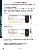
Страница 14: ...to SETTING menu and press SEL REC button to choose the ANGLE you can press UP DOWN to adjust the angle Please visit http magnetic declination com to find out the compass angle of your area 5 1 2 Press SEL REC to select the CALIBRATION the default mode is OFF press DOWN select the AUTO 1 2 3 Drive your vehicle in at least 2 circles counterclockwise allowing 90 seconds to complete one circle 4 Keep ...

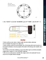
Страница 15: ...bration to function properly The diameter of the driving circle should be close to 5 meters 4 Do not drive too fast when calibrating your pace should be equal to one third normal adult walking speed Complete 2 3 circles to finish the calibration 5 After a new car audio system is installed the compass needs to be recalibrated This is be cause the car s magnetic field has changed 5 Press SEL REC to ...

Страница 16: ...not accurate in some areas A In some areas such as iron mines high intensity magnetic fields change the Earth s magnetism Q Why are old cars more difficult to calibrate than new cars A The older a car is the more magnetized it will be More magnetized cars are more difficult to calibrate and may still have problems after calibration How switch the temperature unit Press the MENU enter into SETTING ...

Страница 17: ...ront of the radiator and the front bumper Slide the metal clip over the edge of the sheet metal or plasic shield until it is secure Do not install the temperature sensor near the engine We do not recommend using the compass in an area with high magnetic lines of flux For example in the north of Canada MAGNETIC FLUXLINE DISTRIBUTION ...

Страница 18: ...RVSSystems 18 MAGNETIC FLUXLINE DISTRIBUTION ...

Страница 19: ...ReverseWithConfidence 19 MAGNETIC FLUXLINE DISTRIBUTION ...

Страница 20: ...Screen Size Display Screen Display Resolution Aspect Ratio Color Depth Pixel Pitch mm Power Consumption WorkingVoltage Video Input Signal System 4 3 TFT LCD 400 H x234 V 16 9 16 7M dithering 0 219x0 219 8W DC12V VIDEO IN to GPS DVD Default Camera to backup camera PAL Auto NTSC ...

Страница 21: ...s tight Verifycameracableispluggedinto port labeled Backup Camera Verify that the green positive trigger on power harness is put to power 12v Verify camera is on correct camera input Verify cable is connected to monitor Verify camera is connected to cable Connect known working camera and cable to monitor Verify Green trigger is receiving power NoImageOnScreen TROUBLESHOOTING ...

Страница 22: ...SYSTEMS INC SYSTEM AFTER PARTIAL FAILURE OR USEWITH IMPROPER ACCESSORIES WARRANTY PERFORMANCE DURINGTHE ABOVEWARRANTY PERIOD SHOULDYOUR RVS SYSTEMS PRODUCT EXHIBIT A DEFECT IN MATERIAL ORWORKMANSHIP SUCH DEFECTWILL BE REPAIREDWHEN THE COMPLETE RVS SYSTEMS INC PRODUCT IS RETURNED POSTAGE PREPAID AND IN SURED TO RVS SYSTEMS INC OTHERTHANTHE POSTAGE AND INSURANCE REQUIREMENT NO CHARGEWILL BE MADE FOR...

Страница 23: ...REARVIEW SAFETY AND OR ITS AFFILIATES SHALL HAVE NO RESPONSIBILITY OR LIABILITY FOR DAMAGE AND OR INJURY RESULTING FROM ACCIDENTS OCCURRING WITH VEHICLES HAVING SOME OF RVS SYSTEMS PRODUCTS INSTALLED AND RVS SYSTEMS AND OR ITS AF FILIATES THE MANUFACTURER DISTRIBUTOR AND SELLER SHALL NOT BE LIABLE FOR ANY INJURY LOSS OR DAMAGE INCIDENTAL OR CONSEQUENTIAL ARISING OUT OF THE USE OR INTENDED USE OFTH...

Страница 24: ...RVSSystems 24 If you have any questions about this product contact RVSSystems Inc 1797AtlanticAvenue Brooklyn NY11233 800 764 1028 BetterCameras BetterService IT SOURGUARANTEE ...

Отзывы: