INSTALLATION, OPERATION, AND MAINTENANCE MANUAL
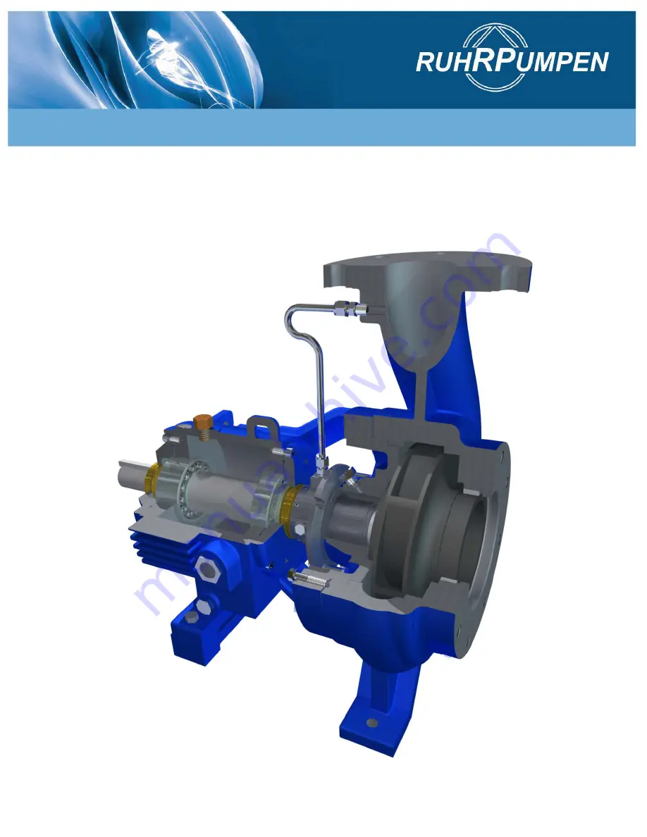
End Suction, Single Stage, Overhung
ANSI/ASME B73.1 - 2001
CPP21
Страница 1: ...INSTALLATION OPERATION AND MAINTENANCE MANUAL End Suction Single Stage Overhung ANSI ASME B73 1 2001 CPP21...
Страница 2: ...ed in the installation care and service of a pump and who as part of their trade education have acquired the ability to interpret and follow the detailed specifications required for such installation...
Страница 3: ...H THE SAFETY INSTRUCTIONS 8 2 4 COMPLIANCE WITH REGULATIONS PERTAINING TO SAFETY AT WORK 8 2 5 SAFETY INSTRUCTIONS RELEVANT FOR OPERATION 8 2 6 SAFETY INSTRUCTIONS RELEVANT FOR MAINTENANCE INSPECTION...
Страница 4: ...ion 33 6 1 3 Quantity 33 6 1 4 Maintenance 34 6 2 OIL CHANGE 34 SECTION SEVEN OPERATION 36 7 1 PRIMING 36 7 2 STARTUP 36 7 3 OPERATING CHECK 37 7 4 DOWELING OPTIONAL 39 7 5 STOPPING 39 7 6 SHORT TERM...
Страница 5: ...ption of the required parts together with their part numbers and identity numbers You can find these on the sectional drawing and spare part list enclosed 1 1 INTRODUCTION Ruhrpumpen pumps of type CPP...
Страница 6: ...3 1 2001 dimensional requirements 1 4 BEARING FRAME The bearing frame which also serves as a large reservoir for oil lubrication encloses the two ball type angular contact thrust and deep groove ball...
Страница 7: ...non compliance would affect personal and equipment safety are identified by the following symbol Where electrical safety is involved the following symbol is shown The symbol is inserted in safety ins...
Страница 8: ...K When operating the pump the safety instructions contained in this manual the relevant national accident prevention regulations local and federal health and safety regulations quality system requirem...
Страница 9: ...completion of work all safety and protective facilities must be re installed and made operative again Prior to restarting the machine follow the instructions listed under SECTION 7 2 STARTUP 2 7 UNAU...
Страница 10: ...the pump check the shipment against the packing list and report damages or shortages immediately to freight carrier and to the designated Ruhrpumpen representative Do not place lifting rig around bear...
Страница 11: ...bject to sudden temperature changes or vibrations Observe the following steps 1 Remove pump from shipping crate but do not damage the crate because the unit is to be reboxed 2 Remove all instruments a...
Страница 12: ...pping crate 13 When the pump is to be installed remove all the protective coatings and desiccant or drain all oils One month before installation a Ruhrpumpen representative should be employed to condu...
Страница 13: ...to overheat since keeping the temperature of the motor frame 9 F 5 C above the surrounding ambient temperature is sufficient After the storing period follow the next steps as start up preparations 1 M...
Страница 14: ...osive layer become damaged it can be repaired by repainting or respraying Anticorrosive layers inside the pump housing must be removed with process neutral solvents before commencing pump operation Wh...
Страница 15: ...d higher than both static and dynamic loads together 2 The effects of vibrating equipment on the surrounding area should be investigated and the isolation required for the foundation should be conside...
Страница 16: ...nded they should be long enough to allow a minimum of two threads above the nuts 5 Provide pipe enclosures for the bolts which are three or four diameters larger than the bolts 6 Protect area around t...
Страница 17: ...undation bolts be sure to respect the above mentioned clearance between concrete and baseplate SECTION 3 3 TRANSPORT There should be a minimum annular clearance of 1 8 inch 3 mm between anchor bolt ho...
Страница 18: ...ing hub to the pump coupling hub 4 3 2 Grouting Precautions During all the grouting process the involved personnel must follow these safety precautions 1 Wear goggles or face shields aprons and protec...
Страница 19: ...ate Do not plug any baseplate fill or vent holes until the grout has set to avoid baseplate distortion Check with the supplier of the grout the preferred thickness for your installation 4 Tap baseplat...
Страница 20: ...tallation Operation and Maintenance Manual CPP21 9 Use a lifting rig to position the pump and driver on their baseplate so that the mounting feet line up with their respective tapped holes 10 Fasten t...
Страница 21: ...en performed In a new installation great care should be taken to prevent dirt scale welding beads and other items from entering the pump The suction system should be thoroughly flushed before installi...
Страница 22: ...installed between 5 to 20 pipe diameters upstream from the suction flange 7 Cone type strainers otherwise known as witches hat strainers should be mounted as recommended within the Hydraulic Institute...
Страница 23: ...ameters of the suction flange should be fitted Do not install unsupported piping on the pump Make sure electrical connections do not impose any stress on the pump unit Remember that the pump must not...
Страница 24: ...he set up onto a rigid piece of pipe rolling the indicator from top to bottom and reading the difference Once the indicator sag set up has been determined this number can be algebraically subtracted f...
Страница 25: ...GRAPHICAL ANALYSIS On a sheet of graph paper lay out the equipment that you are trying to align You should use a scale that is convenient to the size of the graph paper The distances that are critica...
Страница 26: ...127 mm The 0 005 inch 0 127 mm was subtracted from the 0 025 inch 0 639 mm indicator reading to give an actual 0 020 inch 0 508 mm reading As this is a TIR Total Indicator Readout it is two times the...
Страница 27: ...ng is then corrected for indicator sag The 0 005 inch 0 127 mm was subtracted from the 0 005 inch 0 127 mm indicator reading to give an actual 0 010 inch 0 254 mm reading The 0 010 inch 0 254 mm is di...
Страница 28: ...r alignment graphical analysis C REVERSE INDICATOR ALIGNMENT MORE THAN TWO UNITS GRAPHICAL ANALYSIS This method lends itself very well in solving alignment problems of three or more pieces of equipmen...
Страница 29: ...mm 3 Distance from the center of the motor front feet to the center of the motor back feet In this example it is 5 1 4 inches 133 4 mm 4 Distance from disc pack to dial indicator on center member In...
Страница 30: ...be 0 004 inch 0 102 mm The 0 004 inch 0 102 mm was subtracted from 0 025 inch 0 635 mm indicator reading to give an actual of 0 020 inch 0 508 mm reading As this is a TIR Total Indicator Reading it is...
Страница 31: ...so actual is 0 006 inch 0 152 mm What we are trying to do here is determine the angle the center member makes with respect to the motor shaft The minus reading on the bottom indicates that the center...
Страница 32: ...motor should be shimmed up 0 013 inch 0 330 mm under front feet and shimmed up 0 016 inch 0 406 mm under back feet This solution can also be done by use of a pre programmed calculator for faster resu...
Страница 33: ...he bearing frame through the breather connection located at the top of the bearing frame leaving an amount equal to the capacity of constant level oiler bottle apart The correct level is observed in t...
Страница 34: ...ings have been exposed to dirt or moisture thoroughly clean the bearings and frame with a solvent and air dry the parts before adding lubricant Disassembly inspection cleaning and reassembly procedure...
Страница 35: ...frame with a suitable cleaning liquid Flushing the bearing frame with clean lightweight oil is possible 3 Remove the breather connection located at the top of the bearing frame and pour the oil leavi...
Страница 36: ...operating temperature Circulation can be easily accomplished by guiding a small amount of flow from the discharge side of the system beyond the check valve via a multiple breakdown orifice into the bo...
Страница 37: ...10 Uncouple the driver and the pump 11 Start and IMMEDIATELY STOP the driver and observe the rotation of the shaft 12 Correct rotation should be in direction of rotation arrow If shaft rotation is in...
Страница 38: ...s and instruments for proper working order Check all equipment for proper lubrication and correct rotation Check the oil level and validate that the correct oil grade is installed Check that the pumpi...
Страница 39: ...mp as defined in SECTION 7 2 STARTUP 7 5 STOPPING 1 Throttle pump discharge to minimum flow Warning do not close suction valve this will cause the pump to run dry 2 Turn the power off to the driver 3...
Страница 40: ...ssible danger it must be checked for damage 7 7 LONG TERM SHUTDOWN 1 Follow the stopping procedure described in SECTION 7 5 STOPPING 2 Disconnect the vent filter and seal openings on the bearing frame...
Страница 41: ...SASSEMBLY 1 Stop the pump See SECTION 7 5 STOPPING 2 Drain all possible fluids from the pump case and power frames 3 Disconnect any auxiliary piping and wiring that could interfere with disassembly 4...
Страница 42: ...the removal and replacement of pump half coupling Use a puller tool to remove the pump half coupling Use a safe heating method and provide protection for personnel handling the heated half coupling b...
Страница 43: ...assembled in the shaft they must be removed from their packaging and the preservative in the outside diameter and the bore must be wiped out Bearings should be demagnetized before mounting them to av...
Страница 44: ...e 8 2 Positioning the thrust bearing Wear sufficient hand protection to avoid personal injury Important Wait until the bearing has cooled down to room temperature before starting the next step This co...
Страница 45: ...her at full stop Figure 8 4 Positioning the locknut 6 Now take the shaft out of the press and turn it over 180 place it back in the press to reassemble the radial bearing a Place the radial bearing in...
Страница 46: ...tay in place to room temperature Wear sufficient hand protection to avoid personal injury Protect the bearings with oil and cling wrap plastic if you are not going to continue the assembling process i...
Страница 47: ...e by hand using a spanner wrench Ensure at the end of the tightening process that one of the lock washer tabs lines up with the slot in the locknut Figure 8 8 Tightening the locknut 10 The tab that al...
Страница 48: ...is recommended grease is NOT recommended Figure 8 10 Lubricating the labyrinth seal b Position the labyrinth seal at the bearing cover in its correct position with the internal drain slot of the labyr...
Страница 49: ...the radial o ring at the cover Position manually the cover on the power frame ensuring the cover is rotated in the correct position Figure 8 14 Positioning the radial o ring 13 To position the radial...
Страница 50: ...me After this assembly the shaft must be able to rotate by hand however there is some resistance to make it turn due to the action of the labyrinth seals 15 To position the thrust cover at the power f...
Страница 51: ...seal 17 Slide cover onto the shaft ensuring cover is rotated to the correct position do not use a hammer 18 Position the bolts manually Tighten these bolts diagonally crosswise to ensure correct reass...
Страница 52: ...lug installed no thread should remain free after this step 20 Install the plugs in the case cover Figure 8 21 Identifying the plugs in the case cover Apply pipe tape sealant only if it is a pass throu...
Страница 53: ...ngs of the impeller b Insert the wear ring completely in the shoulder of the case using a press Figure 8 24 Positioning the wear ring c Insert the wear ring completely in the shoulder of the case cove...
Страница 54: ...l seal ring b Grease the joint of the mechanical seal head and install it in the internal diameter Figure 8 27 Positioning the mechanical seal joint c Insert the mechanical seal head in the shaft unti...
Страница 55: ...CPP21 Figure 8 29 Positioning the rotary face e Install the spring in the shaft Figure 8 30 Positioning the spring in the shaft f Install the two set screws in the spacer Figure 8 31 Positioning the...
Страница 56: ...g the spacer h Tighten the set screws to set the spacer in that position Figure 8 33 Fixing the spacer in the shaft 23 To install the four studs in the case cover follow these steps a Place the four s...
Страница 57: ...01 Installation Operation and Maintenance Manual CPP21 Figure 8 35 Paired nuts to tighten the stud c Tighten both nuts as shown Figure 8 36 Tightening the paired nuts d Use the spanner to tighten the...
Страница 58: ...8 38 Removing the nuts f Repeat these steps to tighten each of the remaining studs 24 Install the case cover in the power frame Figure 8 39 Installing the case cover 25 Position the screws to hold the...
Страница 59: ...the impeller to tighten it to the possible extent Figure 8 41 Locking the shaft rotation 28 Install the studs and nuts in the mechanical seal head Figure 8 42 Setting the mechanical seal 29 Place the...
Страница 60: ...ure the correct assembly Make sure that the vent of the power frame is oriented towards the discharge of the pump Inspection point Rotate the shaft and make sure the wear rings do not make contact Aft...
Страница 61: ...r side covers 3 Position both components in the lower side of the coupling Insert the bolt of the lower cover in one of the frame supports as shown Tighten the inch 12 7 mm nut by hand to support the...
Страница 62: ...upper cover and insert the two bolts in the upper frame supports Install the nuts to secure the coupling guard assembly and tighten by hand Figure 8 48 Positioning and securing upper pump side cover...
Страница 63: ...e Manual CPP21 7 Before tightening all bolts and nuts with a spanner adjust the length of the coupling guard to close the distance between the coupling guard and the motor to approximately inch 3 175...
Страница 64: ...1 1 2 2 3 30 Case wear ring impeller ring 2 2 2 3 3 4 50 Shaft with fitting key 1 1 2 2 2 3 30 Bearing 1 1 2 2 3 4 50 Bearing frame complete with shaft bearings etc 1 2 Gasket for pump case Sets 4 6 8...
Страница 65: ...Manual CPP21 Material Storage of spare parts Store the spare parts in their original packaging Store in a dry place preferably at a constant temperature Check the spare parts and the state of the pac...
Страница 66: ...23 Axial Labyrinth Seal 160 Case Cover 400 Case Gasket 471 Mechanical Seal Head 210 Shaft 330 Bearing Frame 670 Breather 361 Axial Bearing Cover 564 Radiator Plug 360 Radial Bearing Cover 625 Oil Sigh...
Страница 67: ...yrinth Seal 160 Case Cover 400 Case Gasket 471 Mechanical Seal Head 210 Shaft 330 Bearing Bracket 942 Key 361 Axial Bearing Cover 670 Breather 360 Radial Bearing Cover 564 Radiator Plug 412 1 Axial Co...
Страница 68: ...th Seal 160 Case Cover 400 Case Gasket 471 Mechanical Seal Head 210 Shaft 330 Bearing Bracket 670 Breather 361 Axial Bearing Cover 564 Radiator Plug 360 Radial Bearing Cover 625 Oil Sight 412 1 Axial...
Страница 69: ...nd give the correct spacing PUMP DOES NOT DELIVER LIQUID a Inner pump parts are worn b Density or viscosity of pumped fluid is not same as designed c The motor voltage is incorrect d Motor runs only i...
Страница 70: ...up h Clean pipe and impeller i Install vent valve or lay piping elsewhere j Change worn parts k Consult a Ruhrpumpen dealer l Apply correct voltage to the motor m Check the cables connections and fus...
Страница 71: ...Strasse 28 58453 Witten Germany P O BOX 6309 58432 Witten Germany Phone 49 2302 661 03 MEXICO RUHRPUMPEN S A de C V N quel No 9204 Ciudad Industrial Mitras Garc a NL M xico 66000 Phone 52 81 8158 550...
Страница 72: ...72 72 Horizontal End Suction Pump for Chemical Process ASME B73 1 2001 Installation Operation and Maintenance Manual CPP21 SEPTEMBER 2010...